


Chapter 2
2-8
2.2
Unpacking and
Installation
2.2.1
Unpacking and
Removing the Packaging
Materials
0006-6724
iR2270 / iR2870 / iR3570 / iR4570
1) Unpack and remove the plastic bags.
- When installing a pedestal to the copier at the same
time, unpack it in the same way.
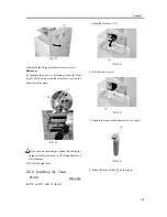
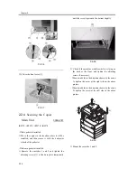
2) When installing the copier on the 2-cassette
Pedestal-Y2, open the right door [1] of the pedestal.
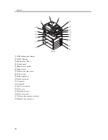
3) Hold the recesses [2] of the copier with 4 or more
people, and place it on the pedestal.
F-2-8
The maximum weight of the copier is approx. 80kg
(including the DADF), so be sure to lift it with 4 or
more people.
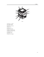
Memo: When placing the copier on the cassette
pedestal, be sure to align the two positioning pins [1]
to the holes on the base plate of the copier.
F-2-9
4) Close the right door of the pedestal (in the case of
the 2-cassette Pedestal-Y2).
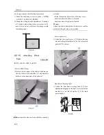
5) Remove the packaging tapes and materials from
each unit.
- Front door
- Right door
- Manual feeder unit
- Cassettes 1 and 2
- Inside the cassettes 1 and 2
- DADF (In the case of the model with a DADF)
- Platen glass
6) When installing the copier to the 2-cassette
Pedestal-Y2, follow the installation procedure for
the 2-cassette Pedestal-Y2.
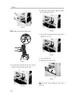
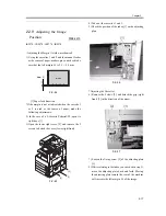
7) Remove the optical system fixing screw [1] at the
outside of the right cover in the reader unit. (Keep
the optical system fixing screw for future relocation
of the copier.)
F-2-10
8) Open the right door [1].
Summary of Contents for iR4570 Series
Page 2: ...Download Free Service Manual And Resetter Printer at http printer1 blogspot com ...
Page 6: ...Download Free Service Manual And Resetter Printer at http printer1 blogspot com ...
Page 28: ...Download Free Service Manual And Resetter Printer at http printer1 blogspot com ...
Page 81: ...Chapter 2 Installation ...
Page 82: ......
Page 84: ......
Page 106: ...system setup network Ethernet driver setup auto detect ...
Page 126: ...F 2 94 3 2 3 1 ...
Page 127: ...Chapter 3 Basic Operation ...
Page 128: ......
Page 130: ......
Page 136: ......
Page 137: ...Chapter 4 Main Controller ...
Page 138: ......
Page 140: ......
Page 164: ......
Page 165: ...Chapter 5 Original Exposure System ...
Page 166: ......
Page 213: ...Chapter 6 Laser Exposure ...
Page 214: ......
Page 216: ......
Page 230: ......
Page 231: ...Chapter 7 Image Formation ...
Page 232: ......
Page 236: ......
Page 249: ...F 7 13 1 2 3 4 ...
Page 308: ......
Page 309: ...Chapter 8 Pickup Feeding System ...
Page 310: ......
Page 316: ......
Page 464: ......
Page 465: ...Chapter 9 Fixing System ...
Page 466: ......
Page 501: ...Chapter 10 External and Controls ...
Page 502: ......
Page 506: ......
Page 564: ......
Page 565: ...Chapter 11 MEAP ...
Page 566: ......
Page 568: ......
Page 573: ...Chapter 12 Maintenance and Inspection ...
Page 574: ......
Page 576: ......
Page 612: ......
Page 613: ...Chapter 13 Standards and Adjustments ...
Page 614: ......
Page 616: ......
Page 635: ...Chapter 14 Correcting Faulty Images ...
Page 636: ......
Page 675: ...T 14 22 Notation Description VR201 for factory use ...
Page 676: ......
Page 677: ...Chapter 15 Self Diagnosis ...
Page 678: ......
Page 680: ......
Page 757: ...Chapter 16 Service Mode ...
Page 758: ......
Page 760: ...Contents 16 8 1 COPIER 16 102 16 8 1 1 Copier List 16 102 ...
Page 869: ...Chapter 17 Service Tools ...
Page 870: ......
Page 871: ...Contents Contents 17 1 Special Tools 17 1 17 2 Oils and Solvents 17 2 ...
Page 872: ......
Page 875: ...Oct 8 2004 ...
Page 876: ......


