


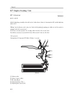


Chapter 8
8-27
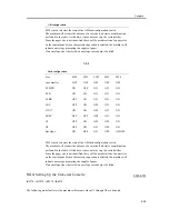
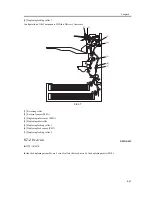
8.4.2
Basic Sequence
0007-7947
iR2270 / iR2870 / iR3570 / iR4570
- Basic Sequence of Operation for Making 3 Prints
F-8-25
8.4.3
Identifying the Paper Size
0007-8700
iR2270 / iR2870 / iR3570 / iR4570
The size of paper inside the cassette is detected by the cassette size dial, and is communicated to the cassette size
detection PCB.
As may as 15 positions may be detected with reference to the combinations of on and off states of the array of 4
actuators mounted to the cassette size detection PCB on the printer side and operating in conjunction with the cassette
size dial.
In the absence of a cassette, all 4 actuators are off, causing the machine to assume there is no cassette.
AB/Inch Switch
The cassette size dial is equipped with a switch operated to change between AB and Inch configurations; the cassette
size detecting switch will detect the configuration as soon as a cassette is fitted in the machine.
Print Start
Cassette 1 pickup motor
(M6)
Cassette 1 pickup
solenoid (SL1)
Cassette 1 retry sensor
(PS10)
Main motor (M2)
Registration sensor
(PS9)
Registration clutch
(CL2)
Fixing motor
(M11)
Fixing/delivery paper
sensor (PS13)
No.1 delivery motor
(M4)
Delivery sensor 1
(PS14)
*1
*3
*2
*1
pickup
*3
registration
*2
pre-registration
cassette 1 pickup motor rotation
increased
cassette 1: 3 sheets of paper
Summary of Contents for iR4570 Series
Page 2: ...Download Free Service Manual And Resetter Printer at http printer1 blogspot com ...
Page 6: ...Download Free Service Manual And Resetter Printer at http printer1 blogspot com ...
Page 28: ...Download Free Service Manual And Resetter Printer at http printer1 blogspot com ...
Page 81: ...Chapter 2 Installation ...
Page 82: ......
Page 84: ......
Page 106: ...system setup network Ethernet driver setup auto detect ...
Page 126: ...F 2 94 3 2 3 1 ...
Page 127: ...Chapter 3 Basic Operation ...
Page 128: ......
Page 130: ......
Page 136: ......
Page 137: ...Chapter 4 Main Controller ...
Page 138: ......
Page 140: ......
Page 164: ......
Page 165: ...Chapter 5 Original Exposure System ...
Page 166: ......
Page 213: ...Chapter 6 Laser Exposure ...
Page 214: ......
Page 216: ......
Page 230: ......
Page 231: ...Chapter 7 Image Formation ...
Page 232: ......
Page 236: ......
Page 249: ...F 7 13 1 2 3 4 ...
Page 308: ......
Page 309: ...Chapter 8 Pickup Feeding System ...
Page 310: ......
Page 316: ......
Page 464: ......
Page 465: ...Chapter 9 Fixing System ...
Page 466: ......
Page 501: ...Chapter 10 External and Controls ...
Page 502: ......
Page 506: ......
Page 564: ......
Page 565: ...Chapter 11 MEAP ...
Page 566: ......
Page 568: ......
Page 573: ...Chapter 12 Maintenance and Inspection ...
Page 574: ......
Page 576: ......
Page 612: ......
Page 613: ...Chapter 13 Standards and Adjustments ...
Page 614: ......
Page 616: ......
Page 635: ...Chapter 14 Correcting Faulty Images ...
Page 636: ......
Page 675: ...T 14 22 Notation Description VR201 for factory use ...
Page 676: ......
Page 677: ...Chapter 15 Self Diagnosis ...
Page 678: ......
Page 680: ......
Page 757: ...Chapter 16 Service Mode ...
Page 758: ......
Page 760: ...Contents 16 8 1 COPIER 16 102 16 8 1 1 Copier List 16 102 ...
Page 869: ...Chapter 17 Service Tools ...
Page 870: ......
Page 871: ...Contents Contents 17 1 Special Tools 17 1 17 2 Oils and Solvents 17 2 ...
Page 872: ......
Page 875: ...Oct 8 2004 ...
Page 876: ......


