

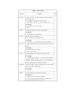


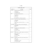


PCL-COPY
Supporting the PCL command [COPIES Meru/Pinatubo/Hood]
2
<Setting range>
0: Control each page according to the command of the COPIES
command specified to the page [Default]
1: Meru/Pinatubo/Hood compatible mode
2 to 65535: Reserved
PRJOB-CP
Setting the CCV count pulse at reception and report output
2
<Setting range>
0: Do not output count pulse [Default]
1: Output count pulse
DPT-ID-7
Registering the department ID and entering 7 digits for
authentication
2
<Setting range>
0: Conventional [Default]
1: 7-digit input
RUI-RJT
Disconnecting the HTTP port from RUI by three authentication
failures
2
<Setting procedure>
0: Invalid [Default]
1: Valid
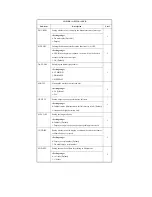
CTM-S06
Setting whether or not to erase the password from the export file of
the file send address
2
<Setting range>
0: Do not erase the password from the export file. [Default]
1: Erase the password from the export file.
CTM-S07
Setting whether or not to erase the RUI address display or the send
password source display on the edit screen
2
<Setting range>
0: Do not erase the send password source display on the edit screen.
[Default]
1: Erase the send password source display on the edit screen.
FREG-SW
Setting whether or not to display the free section of the MEAP
counter (SEND)
2
<Setting range>
0: Do not display [Default]
1: Display
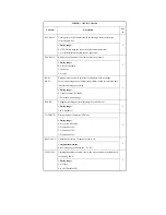
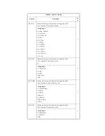
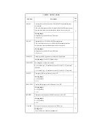
COPIER > OPTION >USER
Sub-item
Description
Level
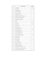
Summary of Contents for iR4570 Series
Page 2: ...Download Free Service Manual And Resetter Printer at http printer1 blogspot com ...
Page 6: ...Download Free Service Manual And Resetter Printer at http printer1 blogspot com ...
Page 28: ...Download Free Service Manual And Resetter Printer at http printer1 blogspot com ...
Page 81: ...Chapter 2 Installation ...
Page 82: ......
Page 84: ......
Page 106: ...system setup network Ethernet driver setup auto detect ...
Page 126: ...F 2 94 3 2 3 1 ...
Page 127: ...Chapter 3 Basic Operation ...
Page 128: ......
Page 130: ......
Page 136: ......
Page 137: ...Chapter 4 Main Controller ...
Page 138: ......
Page 140: ......
Page 164: ......
Page 165: ...Chapter 5 Original Exposure System ...
Page 166: ......
Page 213: ...Chapter 6 Laser Exposure ...
Page 214: ......
Page 216: ......
Page 230: ......
Page 231: ...Chapter 7 Image Formation ...
Page 232: ......
Page 236: ......
Page 249: ...F 7 13 1 2 3 4 ...
Page 308: ......
Page 309: ...Chapter 8 Pickup Feeding System ...
Page 310: ......
Page 316: ......
Page 464: ......
Page 465: ...Chapter 9 Fixing System ...
Page 466: ......
Page 501: ...Chapter 10 External and Controls ...
Page 502: ......
Page 506: ......
Page 564: ......
Page 565: ...Chapter 11 MEAP ...
Page 566: ......
Page 568: ......
Page 573: ...Chapter 12 Maintenance and Inspection ...
Page 574: ......
Page 576: ......
Page 612: ......
Page 613: ...Chapter 13 Standards and Adjustments ...
Page 614: ......
Page 616: ......
Page 635: ...Chapter 14 Correcting Faulty Images ...
Page 636: ......
Page 675: ...T 14 22 Notation Description VR201 for factory use ...
Page 676: ......
Page 677: ...Chapter 15 Self Diagnosis ...
Page 678: ......
Page 680: ......
Page 757: ...Chapter 16 Service Mode ...
Page 758: ......
Page 760: ...Contents 16 8 1 COPIER 16 102 16 8 1 1 Copier List 16 102 ...
Page 869: ...Chapter 17 Service Tools ...
Page 870: ......
Page 871: ...Contents Contents 17 1 Special Tools 17 1 17 2 Oils and Solvents 17 2 ...
Page 872: ......
Page 875: ...Oct 8 2004 ...
Page 876: ......


