
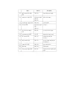


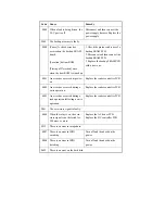


0002 The reading of the sub thermistor
is 295 deg C or more
continuously for 200 msec.
Reset the condition in service
mode:
COPIER>FUNCTION>CLEAR>
ERR. Replace the sub thermistor.
Replace the DC controller PCB.
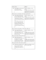
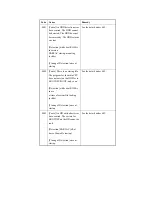
E002
The rise in temperature of the fixing assembly is faulty.
0000 While startup control is under
way, the reading of the main
thermistor is less than 115 deg C
continuously for 400 msec 1.3
sec after it has indicated 100 deg
C.
While startup control is under
way, the reading of the main
thermistor is less than 150 deg C
continuously for 400 msec 1.3
sec after it has indicated 140 deg
C.
Reset the condition in service
mode:
COPIER>FUNCTION>CLEAR>
ERR. Replace the main thermistor.
Replace the DC controller PCB.
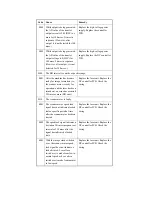
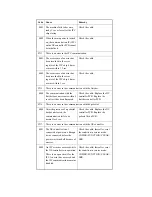
E003
The fixing temperature is too low after a standby state.
0000 While regular temperature
control is under way, the reading
of the main thermistor is less
than 140 deg C continuously for
400 msec or more.
Reset the condition in service
mode:
COPIER>FUNCTION>CLEAR>
ERR. Replace the main thermistor.
Replace the DC controller PCB.
E007
The rotation of the fixing film is faulty.
0000 While the fixing motor is
rotating, the marker signal is not
detected for 6 sec with the
reading of the main thermistor
indicating 100 deg C or more.
Reset the condition in service
mode:
COPIER>FUNCTION>CLEAR>
ERR. Replace the main thermistor.
Replace the DC controller PCB.
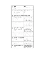
E010
The rotation of the main motor is faulty.
0001 Detection is executed every 100
msec after the start of motor
rotation; however, the drive
detection signal is absent for 2
sec.
Replace the main motor. Replace
the DC controller PCB.
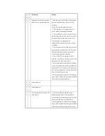
Code
Cause
Remedy
Summary of Contents for iR4570 Series
Page 2: ...Download Free Service Manual And Resetter Printer at http printer1 blogspot com ...
Page 6: ...Download Free Service Manual And Resetter Printer at http printer1 blogspot com ...
Page 28: ...Download Free Service Manual And Resetter Printer at http printer1 blogspot com ...
Page 81: ...Chapter 2 Installation ...
Page 82: ......
Page 84: ......
Page 106: ...system setup network Ethernet driver setup auto detect ...
Page 126: ...F 2 94 3 2 3 1 ...
Page 127: ...Chapter 3 Basic Operation ...
Page 128: ......
Page 130: ......
Page 136: ......
Page 137: ...Chapter 4 Main Controller ...
Page 138: ......
Page 140: ......
Page 164: ......
Page 165: ...Chapter 5 Original Exposure System ...
Page 166: ......
Page 213: ...Chapter 6 Laser Exposure ...
Page 214: ......
Page 216: ......
Page 230: ......
Page 231: ...Chapter 7 Image Formation ...
Page 232: ......
Page 236: ......
Page 249: ...F 7 13 1 2 3 4 ...
Page 308: ......
Page 309: ...Chapter 8 Pickup Feeding System ...
Page 310: ......
Page 316: ......
Page 464: ......
Page 465: ...Chapter 9 Fixing System ...
Page 466: ......
Page 501: ...Chapter 10 External and Controls ...
Page 502: ......
Page 506: ......
Page 564: ......
Page 565: ...Chapter 11 MEAP ...
Page 566: ......
Page 568: ......
Page 573: ...Chapter 12 Maintenance and Inspection ...
Page 574: ......
Page 576: ......
Page 612: ......
Page 613: ...Chapter 13 Standards and Adjustments ...
Page 614: ......
Page 616: ......
Page 635: ...Chapter 14 Correcting Faulty Images ...
Page 636: ......
Page 675: ...T 14 22 Notation Description VR201 for factory use ...
Page 676: ......
Page 677: ...Chapter 15 Self Diagnosis ...
Page 678: ......
Page 680: ......
Page 757: ...Chapter 16 Service Mode ...
Page 758: ......
Page 760: ...Contents 16 8 1 COPIER 16 102 16 8 1 1 Copier List 16 102 ...
Page 869: ...Chapter 17 Service Tools ...
Page 870: ......
Page 871: ...Contents Contents 17 1 Special Tools 17 1 17 2 Oils and Solvents 17 2 ...
Page 872: ......
Page 875: ...Oct 8 2004 ...
Page 876: ......


