


Chapter 13
13-1
13.1
Image Adjustments
13.1.1
Standards for Image
Position
0007-4812
iR2270 / iR2870 / iR3570 / iR4570
A print made at a magnification of 100% must meet
the following standards for image margin/non-image
width:
- Margin Along the Leading Edge
F-13-1
- Left/Right Image Margin
F-13-2
- Leading Edge Non-Image Width
F-13-3
- Left/Right Non-Image Width
F-13-4
13.1.2
Adjusting the Image
Position
0007-4813
iR2270 / iR2870 / iR3570 / iR4570
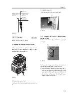
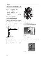
Using the source of paper indicated, make 10 prints
each to see if the image margin and the non-image
margin are as indicated:
[1] Cassettes
[2] Manual feed tray
[3] Side paper deck
If not as indicated, adjust the image position as
follows:
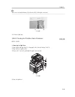
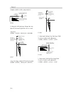
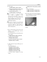
1.Adjusting the Leading Edge Image Margin (1st
side)
Adjust the registration in service mode:
COPIER > ADJUST > FEED-ADJ > REGIST
F-13-5
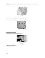
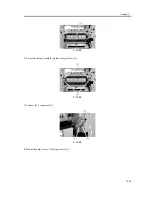
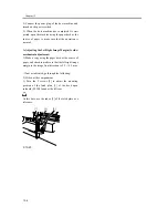
2. Adjusting the Left/Right Image (1st side)
Mechanical Horizontal Registration Adjustment
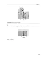
3. Adjusting the Leading Edge Image Margin (2nd
side)
Adjust the registration in service mode:
2
5
4 6 8 10 12 14 16 18 20
0
2.5
1.5mm
2nd side of double-sided copy
2.5
2.0mm
10
8
6
5
4
2
0
2.5
1.5mm
2nd side of double-sided copy
2.5
2.0mm
2
5
4 6 8 10 12 14 16 18 20
0
2.5
1.5mm
2nd side of double-sided copy
2.5
1.5mm
10
8
6
5
4
2
0
2.5
1.5mm
2nd side of double-sided copy
2.5
1.5mm
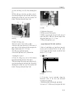
Paper
leading edge
Decrease the REGIST setting.
(a decrease of '10' will
increase the margin by 1 mm)
Increase the REGIST setting.
(an increase of '10' will
increase the margin by 1 mm)
2
5
4 6 8 10 12 14 16 18 20
0
1st side of copy : 2.5 1.5mm
Summary of Contents for iR4570 Series
Page 2: ...Download Free Service Manual And Resetter Printer at http printer1 blogspot com ...
Page 6: ...Download Free Service Manual And Resetter Printer at http printer1 blogspot com ...
Page 28: ...Download Free Service Manual And Resetter Printer at http printer1 blogspot com ...
Page 81: ...Chapter 2 Installation ...
Page 82: ......
Page 84: ......
Page 106: ...system setup network Ethernet driver setup auto detect ...
Page 126: ...F 2 94 3 2 3 1 ...
Page 127: ...Chapter 3 Basic Operation ...
Page 128: ......
Page 130: ......
Page 136: ......
Page 137: ...Chapter 4 Main Controller ...
Page 138: ......
Page 140: ......
Page 164: ......
Page 165: ...Chapter 5 Original Exposure System ...
Page 166: ......
Page 213: ...Chapter 6 Laser Exposure ...
Page 214: ......
Page 216: ......
Page 230: ......
Page 231: ...Chapter 7 Image Formation ...
Page 232: ......
Page 236: ......
Page 249: ...F 7 13 1 2 3 4 ...
Page 308: ......
Page 309: ...Chapter 8 Pickup Feeding System ...
Page 310: ......
Page 316: ......
Page 464: ......
Page 465: ...Chapter 9 Fixing System ...
Page 466: ......
Page 501: ...Chapter 10 External and Controls ...
Page 502: ......
Page 506: ......
Page 564: ......
Page 565: ...Chapter 11 MEAP ...
Page 566: ......
Page 568: ......
Page 573: ...Chapter 12 Maintenance and Inspection ...
Page 574: ......
Page 576: ......
Page 612: ......
Page 613: ...Chapter 13 Standards and Adjustments ...
Page 614: ......
Page 616: ......
Page 635: ...Chapter 14 Correcting Faulty Images ...
Page 636: ......
Page 675: ...T 14 22 Notation Description VR201 for factory use ...
Page 676: ......
Page 677: ...Chapter 15 Self Diagnosis ...
Page 678: ......
Page 680: ......
Page 757: ...Chapter 16 Service Mode ...
Page 758: ......
Page 760: ...Contents 16 8 1 COPIER 16 102 16 8 1 1 Copier List 16 102 ...
Page 869: ...Chapter 17 Service Tools ...
Page 870: ......
Page 871: ...Contents Contents 17 1 Special Tools 17 1 17 2 Oils and Solvents 17 2 ...
Page 872: ......
Page 875: ...Oct 8 2004 ...
Page 876: ......


