


Chapter 5
5-4
5.1.3
Construction of the Control System
0006-5715
iR2270 / iR2870 / iR3570 / iR4570
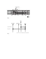
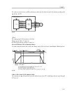
The machine's control system is constructed as follows:
F-5-2
[1] Connection to ADF
[2] Connection to printer body
[3] Printer body (connected to main controller PCB)
[4] Connection to ADF
[5] Reader controller PCB
[6] Reader motor drive control
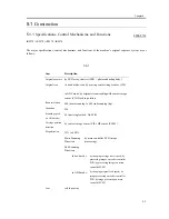
[10]
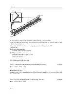
Contact image sensor
(CIS)
-
uses LEDs for indirect exposure (LED +
photoconducting body)
[11]
CIS HP sensor
PS503
photo interrupter: detects CIS home
position
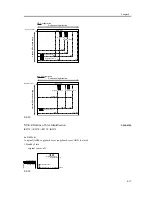
[12]
Cupboard cover
open/closed sensor
PS502
ends original size identification with the
copyboard cover at 5 deg.
*Optional. (100/230-V model only).
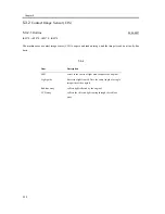
Item
Notation
Description
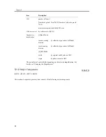
J500
J501
J505
J502
J510
J508
J506
J507
J503
/504
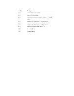
[10]
[8]
[4]
[1]
Summary of Contents for iR4570 Series
Page 2: ...Download Free Service Manual And Resetter Printer at http printer1 blogspot com ...
Page 6: ...Download Free Service Manual And Resetter Printer at http printer1 blogspot com ...
Page 28: ...Download Free Service Manual And Resetter Printer at http printer1 blogspot com ...
Page 81: ...Chapter 2 Installation ...
Page 82: ......
Page 84: ......
Page 106: ...system setup network Ethernet driver setup auto detect ...
Page 126: ...F 2 94 3 2 3 1 ...
Page 127: ...Chapter 3 Basic Operation ...
Page 128: ......
Page 130: ......
Page 136: ......
Page 137: ...Chapter 4 Main Controller ...
Page 138: ......
Page 140: ......
Page 164: ......
Page 165: ...Chapter 5 Original Exposure System ...
Page 166: ......
Page 213: ...Chapter 6 Laser Exposure ...
Page 214: ......
Page 216: ......
Page 230: ......
Page 231: ...Chapter 7 Image Formation ...
Page 232: ......
Page 236: ......
Page 249: ...F 7 13 1 2 3 4 ...
Page 308: ......
Page 309: ...Chapter 8 Pickup Feeding System ...
Page 310: ......
Page 316: ......
Page 464: ......
Page 465: ...Chapter 9 Fixing System ...
Page 466: ......
Page 501: ...Chapter 10 External and Controls ...
Page 502: ......
Page 506: ......
Page 564: ......
Page 565: ...Chapter 11 MEAP ...
Page 566: ......
Page 568: ......
Page 573: ...Chapter 12 Maintenance and Inspection ...
Page 574: ......
Page 576: ......
Page 612: ......
Page 613: ...Chapter 13 Standards and Adjustments ...
Page 614: ......
Page 616: ......
Page 635: ...Chapter 14 Correcting Faulty Images ...
Page 636: ......
Page 675: ...T 14 22 Notation Description VR201 for factory use ...
Page 676: ......
Page 677: ...Chapter 15 Self Diagnosis ...
Page 678: ......
Page 680: ......
Page 757: ...Chapter 16 Service Mode ...
Page 758: ......
Page 760: ...Contents 16 8 1 COPIER 16 102 16 8 1 1 Copier List 16 102 ...
Page 869: ...Chapter 17 Service Tools ...
Page 870: ......
Page 871: ...Contents Contents 17 1 Special Tools 17 1 17 2 Oils and Solvents 17 2 ...
Page 872: ......
Page 875: ...Oct 8 2004 ...
Page 876: ......


