


Chapter 16
16-50
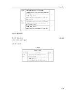
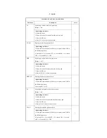
T-16-36
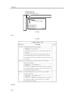
<PANEL>
T-16-37
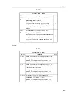
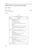
COPIER > FUNCTION > FIXING
Sub-item
Description
Level
NIP-CHK
Making output for measuring the fixing nip width automatically
1
<Operating procedure>
1) Register Plain Paper or Recycled Paper for the manual feed tray.
(User mode: Setting Common Specifications>Registering Paper Type).
2) Place plain paper or recycled paper of the A4 (LTR) size on the
manual feed tray.
3) Select this service mode and press the OK key (to feed paper from
the manual feed tray).
4) The fed paper is held once by the fixing roller and ejected after about
10 seconds.
5) Check that the nip width of the ejected paper conforms to the
standard.
Note: This machine does not allow nip width adjustment. This item is
used for nip width checking only.
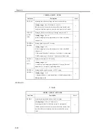
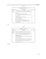
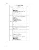
COPIER > FUNCTION > PANEL
Sub-item
Description
Level
LCD-CHK
Checking the LCD display for missing dots
1
<Operating procedure>
1) Select this item and press the OK key to start operation. The front of
the panel lights repeatedly in order of white, black, red, green, and blue.
(Check this lighting.)
2) Press the Stop key to terminate the operation.
LED-CHK
Checking LED lighting in the operating section
1
<Operating procedure>
1) Select this item and press the OK key to start operation. The LED
lamps light sequentially.
2) Press LED-OFF to terminate the operation.
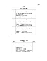
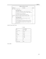
LED-OFF
Checking LED lighting in the operating section
1
<Operating procedure>
1) Select this item to terminate LED-CHK operation.
Summary of Contents for iR4570 Series
Page 2: ...Download Free Service Manual And Resetter Printer at http printer1 blogspot com ...
Page 6: ...Download Free Service Manual And Resetter Printer at http printer1 blogspot com ...
Page 28: ...Download Free Service Manual And Resetter Printer at http printer1 blogspot com ...
Page 81: ...Chapter 2 Installation ...
Page 82: ......
Page 84: ......
Page 106: ...system setup network Ethernet driver setup auto detect ...
Page 126: ...F 2 94 3 2 3 1 ...
Page 127: ...Chapter 3 Basic Operation ...
Page 128: ......
Page 130: ......
Page 136: ......
Page 137: ...Chapter 4 Main Controller ...
Page 138: ......
Page 140: ......
Page 164: ......
Page 165: ...Chapter 5 Original Exposure System ...
Page 166: ......
Page 213: ...Chapter 6 Laser Exposure ...
Page 214: ......
Page 216: ......
Page 230: ......
Page 231: ...Chapter 7 Image Formation ...
Page 232: ......
Page 236: ......
Page 249: ...F 7 13 1 2 3 4 ...
Page 308: ......
Page 309: ...Chapter 8 Pickup Feeding System ...
Page 310: ......
Page 316: ......
Page 464: ......
Page 465: ...Chapter 9 Fixing System ...
Page 466: ......
Page 501: ...Chapter 10 External and Controls ...
Page 502: ......
Page 506: ......
Page 564: ......
Page 565: ...Chapter 11 MEAP ...
Page 566: ......
Page 568: ......
Page 573: ...Chapter 12 Maintenance and Inspection ...
Page 574: ......
Page 576: ......
Page 612: ......
Page 613: ...Chapter 13 Standards and Adjustments ...
Page 614: ......
Page 616: ......
Page 635: ...Chapter 14 Correcting Faulty Images ...
Page 636: ......
Page 675: ...T 14 22 Notation Description VR201 for factory use ...
Page 676: ......
Page 677: ...Chapter 15 Self Diagnosis ...
Page 678: ......
Page 680: ......
Page 757: ...Chapter 16 Service Mode ...
Page 758: ......
Page 760: ...Contents 16 8 1 COPIER 16 102 16 8 1 1 Copier List 16 102 ...
Page 869: ...Chapter 17 Service Tools ...
Page 870: ......
Page 871: ...Contents Contents 17 1 Special Tools 17 1 17 2 Oils and Solvents 17 2 ...
Page 872: ......
Page 875: ...Oct 8 2004 ...
Page 876: ......


