


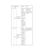
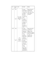


E537
0001
Rear
alignment
error
(Finisher-Q3/
Q4)
The home
position sensor
does not go on
within 2000
msec after the
start of
operation
when the read
aligning plate
is moved to
home position.
Replace the finisher
controller PCB.
Replace the rear
alignment motor.
Check the rear aligning
plate drive mechanism.
Check the rear
alignment home
position sensor.
0002
The home
position sensor
does not go off
within 1000
msec after the
start of
operation
when the rear
aligning plate
is moved form
home position.
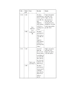
E540
8002
Stack tray
motor error
(Finisher-S1)
The operation
to detect the
paper surface
of the stack
tray does not
end within 1.0
sec.
Replace the finisher
controller PCB.
Replace the tray ascent/
descent motor. Check
the stack tray drive
mechanism. Check the
paper surface sensor.
8003
An abnormal
combination of
sensor states
has been
detected.
Replace the finisher
controller PCB. Check
the stack tray upper
limit sensor. Check the
stack tray lower limit
sensor. Check the stack
tray upper paper
surface sensor. Check
the stack tray lower
paper surface sensor.
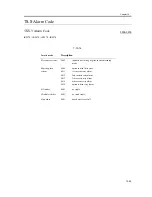
Code
Detail
code
Name
Detection
Remedy
Summary of Contents for iR4570 Series
Page 2: ...Download Free Service Manual And Resetter Printer at http printer1 blogspot com ...
Page 6: ...Download Free Service Manual And Resetter Printer at http printer1 blogspot com ...
Page 28: ...Download Free Service Manual And Resetter Printer at http printer1 blogspot com ...
Page 81: ...Chapter 2 Installation ...
Page 82: ......
Page 84: ......
Page 106: ...system setup network Ethernet driver setup auto detect ...
Page 126: ...F 2 94 3 2 3 1 ...
Page 127: ...Chapter 3 Basic Operation ...
Page 128: ......
Page 130: ......
Page 136: ......
Page 137: ...Chapter 4 Main Controller ...
Page 138: ......
Page 140: ......
Page 164: ......
Page 165: ...Chapter 5 Original Exposure System ...
Page 166: ......
Page 213: ...Chapter 6 Laser Exposure ...
Page 214: ......
Page 216: ......
Page 230: ......
Page 231: ...Chapter 7 Image Formation ...
Page 232: ......
Page 236: ......
Page 249: ...F 7 13 1 2 3 4 ...
Page 308: ......
Page 309: ...Chapter 8 Pickup Feeding System ...
Page 310: ......
Page 316: ......
Page 464: ......
Page 465: ...Chapter 9 Fixing System ...
Page 466: ......
Page 501: ...Chapter 10 External and Controls ...
Page 502: ......
Page 506: ......
Page 564: ......
Page 565: ...Chapter 11 MEAP ...
Page 566: ......
Page 568: ......
Page 573: ...Chapter 12 Maintenance and Inspection ...
Page 574: ......
Page 576: ......
Page 612: ......
Page 613: ...Chapter 13 Standards and Adjustments ...
Page 614: ......
Page 616: ......
Page 635: ...Chapter 14 Correcting Faulty Images ...
Page 636: ......
Page 675: ...T 14 22 Notation Description VR201 for factory use ...
Page 676: ......
Page 677: ...Chapter 15 Self Diagnosis ...
Page 678: ......
Page 680: ......
Page 757: ...Chapter 16 Service Mode ...
Page 758: ......
Page 760: ...Contents 16 8 1 COPIER 16 102 16 8 1 1 Copier List 16 102 ...
Page 869: ...Chapter 17 Service Tools ...
Page 870: ......
Page 871: ...Contents Contents 17 1 Special Tools 17 1 17 2 Oils and Solvents 17 2 ...
Page 872: ......
Page 875: ...Oct 8 2004 ...
Page 876: ......


