
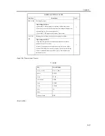


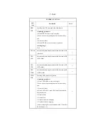


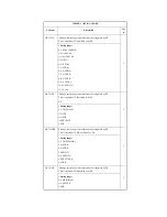


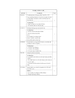


TEMP-CON
Switching thick-paper fixing temperature mode
1
<Setting range>
0: OFF [Default]
1: Priority to productivity, control temperature fixed at -10deg C
2: Control temperature fixed at -6deg C
3: Control temperature fixed at -3deg C
4: Priority to fixing, control temperature fixed at +3deg C
5: Control temperature fixed at +6deg C
6: Control temperature fixed at +10deg C
7: Control temperature fixed at +15deg C
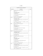
PRIAC-SW
Improving the image quality in case of a drum charging fault
Note: This setting is cleared if APVC is executed with a new drum unit
or if a service mode (FUNCTION>D-GAMMA) is executed.
1
<Setting range>
0: No UP [Default], 1: 50 mA UP, 2: 100 mA UP
TEMPCON2
Improving fixing (Increasing the fixing temperature)
Note: Valid for iR3570/3570F/4570/4570F only
1
<Setting range>
0: OFF [Default]
1: Priority to productivity, control temperature fixed at -10deg C
2: Control temperature fixed at -6deg C
3: Control temperature fixed at -3deg C
4: Priority to fixing, control temperature fixed at +3deg C
5: Control temperature fixed at +6deg C
6: Control temperature fixed at +10deg C
7: Control temperature fixed at +15deg C
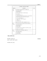
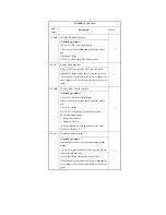
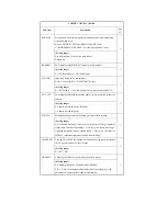
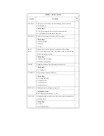
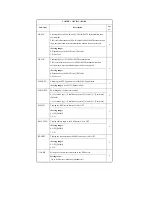
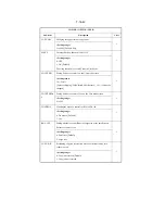
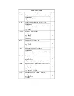
COPIER > OPTION > BODY
Sub-item
Description
Lev
el
Summary of Contents for iR4570 Series
Page 2: ...Download Free Service Manual And Resetter Printer at http printer1 blogspot com ...
Page 6: ...Download Free Service Manual And Resetter Printer at http printer1 blogspot com ...
Page 28: ...Download Free Service Manual And Resetter Printer at http printer1 blogspot com ...
Page 81: ...Chapter 2 Installation ...
Page 82: ......
Page 84: ......
Page 106: ...system setup network Ethernet driver setup auto detect ...
Page 126: ...F 2 94 3 2 3 1 ...
Page 127: ...Chapter 3 Basic Operation ...
Page 128: ......
Page 130: ......
Page 136: ......
Page 137: ...Chapter 4 Main Controller ...
Page 138: ......
Page 140: ......
Page 164: ......
Page 165: ...Chapter 5 Original Exposure System ...
Page 166: ......
Page 213: ...Chapter 6 Laser Exposure ...
Page 214: ......
Page 216: ......
Page 230: ......
Page 231: ...Chapter 7 Image Formation ...
Page 232: ......
Page 236: ......
Page 249: ...F 7 13 1 2 3 4 ...
Page 308: ......
Page 309: ...Chapter 8 Pickup Feeding System ...
Page 310: ......
Page 316: ......
Page 464: ......
Page 465: ...Chapter 9 Fixing System ...
Page 466: ......
Page 501: ...Chapter 10 External and Controls ...
Page 502: ......
Page 506: ......
Page 564: ......
Page 565: ...Chapter 11 MEAP ...
Page 566: ......
Page 568: ......
Page 573: ...Chapter 12 Maintenance and Inspection ...
Page 574: ......
Page 576: ......
Page 612: ......
Page 613: ...Chapter 13 Standards and Adjustments ...
Page 614: ......
Page 616: ......
Page 635: ...Chapter 14 Correcting Faulty Images ...
Page 636: ......
Page 675: ...T 14 22 Notation Description VR201 for factory use ...
Page 676: ......
Page 677: ...Chapter 15 Self Diagnosis ...
Page 678: ......
Page 680: ......
Page 757: ...Chapter 16 Service Mode ...
Page 758: ......
Page 760: ...Contents 16 8 1 COPIER 16 102 16 8 1 1 Copier List 16 102 ...
Page 869: ...Chapter 17 Service Tools ...
Page 870: ......
Page 871: ...Contents Contents 17 1 Special Tools 17 1 17 2 Oils and Solvents 17 2 ...
Page 872: ......
Page 875: ...Oct 8 2004 ...
Page 876: ......


