


Chapter 12
12-9
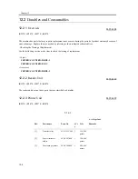
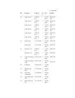
T-12-3
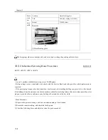
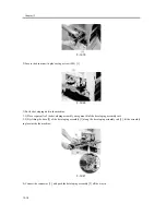
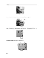
4) Check the waste toner collection case.
If the case is half full or more, empty it in an appropriate bag for collection. Or, replace the waste toner collection
case.
- When disposing of the waste toner, be sure to follow all applicable regulations of the local government.
- Do not dispose of waste toner in fire. (Doing so can cause an explosion.)
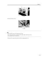
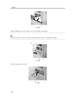
5) Clean the copyboard glass and the reading glass.
6) Make test copies.
7) Make sample copies.
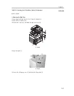
8) Check the operation of the leakage breaker.
While the machine is supplied with power (power switch ON), press the test switch of the leakage breaker to see if
the breaker operates normally (i.e., the lever will shift to OFF to cut off the power).
If the leakage breaker fails to operate normally, replace the breaker, and make a check once again.
<Resetting>
When you have checked the operation of the leakage breaker, turn off the power switch, shift the lever to ON, and
turn on the power switch.
Item
Test copy
image density
background (for soiling)
characters (for clarity)
margin
fixing
misregistration, soiled back
margin (single-sided)
leading edge:2.5±1.5mm
left:2.5±1.5mm
margin (double-sided)
leading edge:2.5±2.0mm
left edge:2.5±2.0mm
Laser exposure
system
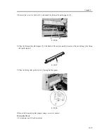
dust-blocking glass (cleaning)
Feeding system
toner/feed guide
fixing inlet guide
Developing
system
developing butting spacer
Summary of Contents for iR4570 Series
Page 2: ...Download Free Service Manual And Resetter Printer at http printer1 blogspot com ...
Page 6: ...Download Free Service Manual And Resetter Printer at http printer1 blogspot com ...
Page 28: ...Download Free Service Manual And Resetter Printer at http printer1 blogspot com ...
Page 81: ...Chapter 2 Installation ...
Page 82: ......
Page 84: ......
Page 106: ...system setup network Ethernet driver setup auto detect ...
Page 126: ...F 2 94 3 2 3 1 ...
Page 127: ...Chapter 3 Basic Operation ...
Page 128: ......
Page 130: ......
Page 136: ......
Page 137: ...Chapter 4 Main Controller ...
Page 138: ......
Page 140: ......
Page 164: ......
Page 165: ...Chapter 5 Original Exposure System ...
Page 166: ......
Page 213: ...Chapter 6 Laser Exposure ...
Page 214: ......
Page 216: ......
Page 230: ......
Page 231: ...Chapter 7 Image Formation ...
Page 232: ......
Page 236: ......
Page 249: ...F 7 13 1 2 3 4 ...
Page 308: ......
Page 309: ...Chapter 8 Pickup Feeding System ...
Page 310: ......
Page 316: ......
Page 464: ......
Page 465: ...Chapter 9 Fixing System ...
Page 466: ......
Page 501: ...Chapter 10 External and Controls ...
Page 502: ......
Page 506: ......
Page 564: ......
Page 565: ...Chapter 11 MEAP ...
Page 566: ......
Page 568: ......
Page 573: ...Chapter 12 Maintenance and Inspection ...
Page 574: ......
Page 576: ......
Page 612: ......
Page 613: ...Chapter 13 Standards and Adjustments ...
Page 614: ......
Page 616: ......
Page 635: ...Chapter 14 Correcting Faulty Images ...
Page 636: ......
Page 675: ...T 14 22 Notation Description VR201 for factory use ...
Page 676: ......
Page 677: ...Chapter 15 Self Diagnosis ...
Page 678: ......
Page 680: ......
Page 757: ...Chapter 16 Service Mode ...
Page 758: ......
Page 760: ...Contents 16 8 1 COPIER 16 102 16 8 1 1 Copier List 16 102 ...
Page 869: ...Chapter 17 Service Tools ...
Page 870: ......
Page 871: ...Contents Contents 17 1 Special Tools 17 1 17 2 Oils and Solvents 17 2 ...
Page 872: ......
Page 875: ...Oct 8 2004 ...
Page 876: ......


