Contents
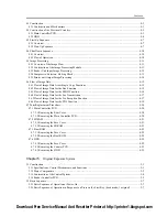
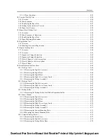
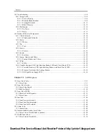
12.3 Scheduled Servicing Basic Procedure........................................................................................................... 12- 5
12.3.1Scheduled Servicing for the Reader Unit ................................................................................................ 12- 5
12.3.2Scheduled Servicing for the Printer Unit ................................................................................................ 12- 5
12.3.3Scheduled Servicing Basic Procedures ................................................................................................... 12- 8
12.3.4Points to Note About the Scheduled Servicing ..................................................................................... 12- 10
12.4 Cleaning....................................................................................................................................................... 12- 12
12.4.1Cleaning the Transfer/Feed Guide ........................................................................................................ 12- 12
12.4.2Cleaning the Developing Assembly Spacer, Feed Guide, Dust-Blocking Glass, and Fixing Inlet Guide. 12-
12
12.4.3Cleaning the Film Bias Static Eliminator.............................................................................................. 12- 21
12.4.4Cleaning the Film Bias Static Eliminator.............................................................................................. 12- 29
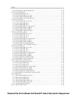
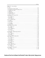
Chapter 13
Standards and Adjustments
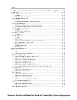
13.1 Image Adjustments........................................................................................................................................ 13- 1
13.1.1Standards for Image Position .................................................................................................................. 13- 1
13.1.2Adjusting the Image Position .................................................................................................................. 13- 1
13.1.3Cassette.................................................................................................................................................... 13- 3
13.1.4Manual Feed Tray ................................................................................................................................... 13- 5
13.1.5Side Paper Deck ...................................................................................................................................... 13- 5
13.2 Scanning System ........................................................................................................................................... 13- 7
13.2.1After Replacement of the CIS ................................................................................................................. 13- 7
13.2.2After Replacing the Reader Controller PCB or Initializing the RAM .................................................... 13- 7
13.3 Laser Exposure System ................................................................................................................................. 13- 9
13.3.1After Replacing the Laser Scanner Unit.................................................................................................. 13- 9
13.4 Image Formation System............................................................................................................................. 13- 10
13.4.1After Replacing the Developing Unit.................................................................................................... 13- 10
13.4.2After Replacing the Drum Unit (APVC correction) ............................................................................. 13- 10
13.5 Electrical Components ................................................................................................................................ 13- 11
13.5.1After Replacing the HDD...................................................................................................................... 13- 11
13.5.2After Replacing the DC Controller PCB............................................................................................... 13- 11
13.5.3After Replacing the Main Controller PCB ............................................................................................ 13- 11
13.5.4After Replacing the Reader Controller PCB ......................................................................................... 13- 12
13.6 Pickup/Feeding System ............................................................................................................................... 13- 14
13.6.1Adjusting the Horizontal Registration When Replacing the Cassette................................................... 13- 14
13.6.2Adjusting the Horizontal Registration When Replacing the Duplex Unit ............................................ 13- 16
13.6.3Adjusting the Manual Feed Pickup Horizontal Registration................................................................. 13- 16
13.6.4Registering the Paper Width Basic Value ............................................................................................. 13- 17
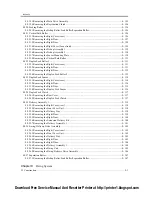
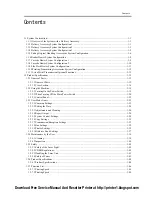
Chapter 14
Correcting Faulty Images
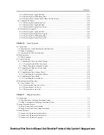
14.1 Making lnitial Checks ................................................................................................................................... 14- 1
14.1.1Site Environment..................................................................................................................................... 14- 1
14.1.2Checking the Paper.................................................................................................................................. 14- 1
14.1.3Checking the Placement of Paper............................................................................................................ 14- 1
14.1.4Checking the Durables ............................................................................................................................ 14- 1
14.1.5Checking the Periodically Serviced Items............................................................................................... 14- 1
14.1.6Checking the Units and Functional Systems........................................................................................... 14- 2
14.1.7Others ...................................................................................................................................................... 14- 3
Download Free Service Manual And Resetter Printer at http://printer1.blogspot.com
Summary of Contents for iR4570 Series
Page 2: ...Download Free Service Manual And Resetter Printer at http printer1 blogspot com ...
Page 6: ...Download Free Service Manual And Resetter Printer at http printer1 blogspot com ...
Page 28: ...Download Free Service Manual And Resetter Printer at http printer1 blogspot com ...
Page 81: ...Chapter 2 Installation ...
Page 82: ......
Page 84: ......
Page 106: ...system setup network Ethernet driver setup auto detect ...
Page 126: ...F 2 94 3 2 3 1 ...
Page 127: ...Chapter 3 Basic Operation ...
Page 128: ......
Page 130: ......
Page 136: ......
Page 137: ...Chapter 4 Main Controller ...
Page 138: ......
Page 140: ......
Page 164: ......
Page 165: ...Chapter 5 Original Exposure System ...
Page 166: ......
Page 213: ...Chapter 6 Laser Exposure ...
Page 214: ......
Page 216: ......
Page 230: ......
Page 231: ...Chapter 7 Image Formation ...
Page 232: ......
Page 236: ......
Page 249: ...F 7 13 1 2 3 4 ...
Page 308: ......
Page 309: ...Chapter 8 Pickup Feeding System ...
Page 310: ......
Page 316: ......
Page 464: ......
Page 465: ...Chapter 9 Fixing System ...
Page 466: ......
Page 501: ...Chapter 10 External and Controls ...
Page 502: ......
Page 506: ......
Page 564: ......
Page 565: ...Chapter 11 MEAP ...
Page 566: ......
Page 568: ......
Page 573: ...Chapter 12 Maintenance and Inspection ...
Page 574: ......
Page 576: ......
Page 612: ......
Page 613: ...Chapter 13 Standards and Adjustments ...
Page 614: ......
Page 616: ......
Page 635: ...Chapter 14 Correcting Faulty Images ...
Page 636: ......
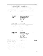
Page 675: ...T 14 22 Notation Description VR201 for factory use ...
Page 676: ......
Page 677: ...Chapter 15 Self Diagnosis ...
Page 678: ......
Page 680: ......
Page 757: ...Chapter 16 Service Mode ...
Page 758: ......
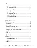
Page 760: ...Contents 16 8 1 COPIER 16 102 16 8 1 1 Copier List 16 102 ...
Page 869: ...Chapter 17 Service Tools ...
Page 870: ......
Page 871: ...Contents Contents 17 1 Special Tools 17 1 17 2 Oils and Solvents 17 2 ...
Page 872: ......
Page 875: ...Oct 8 2004 ...
Page 876: ......

