


Chapter 5
5-24
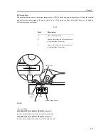
level (offset correction).
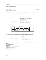
5.3.6.4
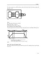
A/D Conversion of the CCD Output
0006-5933
iR2270 / iR2870 / iR3570 / iR4570
The analog video signal is further converted into a digital signal that is suited to the voltage level of individual pixels
by the A/D converter.
5.3.6.5
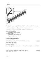
Shading Correction (outline)
0006-5936
iR2270 / iR2870 / iR3570 / iR4570
The output of the CCD is not necessarily even for the following factors even when the density of the original is
uniform:
1) Variation in the Sensitivity Among Pixels of the CCD
2) Variation in the Intensity of the Rod Lens Array
The machine executes shading correction to even out the output of the CCD. Shading correction may be shading
adjustment executed at power-on or shading correction executed for each job.
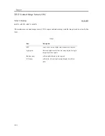
5.3.6.6
Shading Adjustment
0006-5937
iR2270 / iR2870 / iR3570 / iR4570
In this adjustment, the machine measures the density of the standard while plate, and stores the results in memory as
density data. It then performs computations on the shading data, and uses the result as the target value for shading
correction.
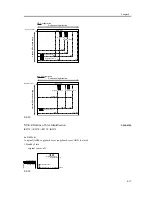
5.3.6.7
Shading Correction
0006-5938
iR2270 / iR2870 / iR3570 / iR4570
The machine executes this correction for every scan made in main shading unit. It measures the density of the
standard white plate, and compares the result against the target value stored in the shading correction circuit; the
difference between the two will be held as the shading correction value for use in correcting variation among CCD
pixels when scanning the original, thus evening out the density levels of the image.
Summary of Contents for iR4570 Series
Page 2: ...Download Free Service Manual And Resetter Printer at http printer1 blogspot com ...
Page 6: ...Download Free Service Manual And Resetter Printer at http printer1 blogspot com ...
Page 28: ...Download Free Service Manual And Resetter Printer at http printer1 blogspot com ...
Page 81: ...Chapter 2 Installation ...
Page 82: ......
Page 84: ......
Page 106: ...system setup network Ethernet driver setup auto detect ...
Page 126: ...F 2 94 3 2 3 1 ...
Page 127: ...Chapter 3 Basic Operation ...
Page 128: ......
Page 130: ......
Page 136: ......
Page 137: ...Chapter 4 Main Controller ...
Page 138: ......
Page 140: ......
Page 164: ......
Page 165: ...Chapter 5 Original Exposure System ...
Page 166: ......
Page 213: ...Chapter 6 Laser Exposure ...
Page 214: ......
Page 216: ......
Page 230: ......
Page 231: ...Chapter 7 Image Formation ...
Page 232: ......
Page 236: ......
Page 249: ...F 7 13 1 2 3 4 ...
Page 308: ......
Page 309: ...Chapter 8 Pickup Feeding System ...
Page 310: ......
Page 316: ......
Page 464: ......
Page 465: ...Chapter 9 Fixing System ...
Page 466: ......
Page 501: ...Chapter 10 External and Controls ...
Page 502: ......
Page 506: ......
Page 564: ......
Page 565: ...Chapter 11 MEAP ...
Page 566: ......
Page 568: ......
Page 573: ...Chapter 12 Maintenance and Inspection ...
Page 574: ......
Page 576: ......
Page 612: ......
Page 613: ...Chapter 13 Standards and Adjustments ...
Page 614: ......
Page 616: ......
Page 635: ...Chapter 14 Correcting Faulty Images ...
Page 636: ......
Page 675: ...T 14 22 Notation Description VR201 for factory use ...
Page 676: ......
Page 677: ...Chapter 15 Self Diagnosis ...
Page 678: ......
Page 680: ......
Page 757: ...Chapter 16 Service Mode ...
Page 758: ......
Page 760: ...Contents 16 8 1 COPIER 16 102 16 8 1 1 Copier List 16 102 ...
Page 869: ...Chapter 17 Service Tools ...
Page 870: ......
Page 871: ...Contents Contents 17 1 Special Tools 17 1 17 2 Oils and Solvents 17 2 ...
Page 872: ......
Page 875: ...Oct 8 2004 ...
Page 876: ......


