


Chapter 5
5-13
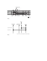
F-5-13
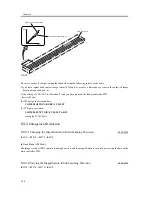
5.3.2.2
Analog Control Inside the Contact Image Sensor
0006-5928
iR2270 / iR2870 / iR3570 / iR4570
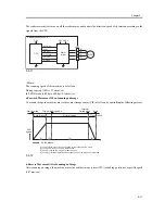
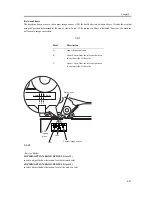
The contact image sensor (CIS) is used to control analog image processing in the following flow of work:
The light reflected by the original is collected by the rod lens array;
the light is then collected by the CCD array;
the light is converted into an electric signal by the CCD array (photo-conversion) for output.
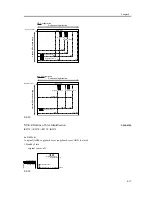
The CCD array consists of a total of 8 channels (units). Each channel possesses its own output correction table used
to process an input intensity signal for gain correction for output of an image signal.
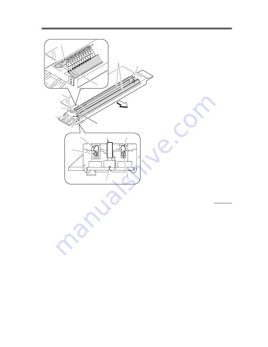
Light guide
Light guide
LED
CCD
LED
Rod lens array
Light guide
LED (R/G/B)
CCD array
Rod lens array
Image read line
Copyboard glass
LED (R/G/B)
scanning direction
Summary of Contents for iR4570 Series
Page 2: ...Download Free Service Manual And Resetter Printer at http printer1 blogspot com ...
Page 6: ...Download Free Service Manual And Resetter Printer at http printer1 blogspot com ...
Page 28: ...Download Free Service Manual And Resetter Printer at http printer1 blogspot com ...
Page 81: ...Chapter 2 Installation ...
Page 82: ......
Page 84: ......
Page 106: ...system setup network Ethernet driver setup auto detect ...
Page 126: ...F 2 94 3 2 3 1 ...
Page 127: ...Chapter 3 Basic Operation ...
Page 128: ......
Page 130: ......
Page 136: ......
Page 137: ...Chapter 4 Main Controller ...
Page 138: ......
Page 140: ......
Page 164: ......
Page 165: ...Chapter 5 Original Exposure System ...
Page 166: ......
Page 213: ...Chapter 6 Laser Exposure ...
Page 214: ......
Page 216: ......
Page 230: ......
Page 231: ...Chapter 7 Image Formation ...
Page 232: ......
Page 236: ......
Page 249: ...F 7 13 1 2 3 4 ...
Page 308: ......
Page 309: ...Chapter 8 Pickup Feeding System ...
Page 310: ......
Page 316: ......
Page 464: ......
Page 465: ...Chapter 9 Fixing System ...
Page 466: ......
Page 501: ...Chapter 10 External and Controls ...
Page 502: ......
Page 506: ......
Page 564: ......
Page 565: ...Chapter 11 MEAP ...
Page 566: ......
Page 568: ......
Page 573: ...Chapter 12 Maintenance and Inspection ...
Page 574: ......
Page 576: ......
Page 612: ......
Page 613: ...Chapter 13 Standards and Adjustments ...
Page 614: ......
Page 616: ......
Page 635: ...Chapter 14 Correcting Faulty Images ...
Page 636: ......
Page 675: ...T 14 22 Notation Description VR201 for factory use ...
Page 676: ......
Page 677: ...Chapter 15 Self Diagnosis ...
Page 678: ......
Page 680: ......
Page 757: ...Chapter 16 Service Mode ...
Page 758: ......
Page 760: ...Contents 16 8 1 COPIER 16 102 16 8 1 1 Copier List 16 102 ...
Page 869: ...Chapter 17 Service Tools ...
Page 870: ......
Page 871: ...Contents Contents 17 1 Special Tools 17 1 17 2 Oils and Solvents 17 2 ...
Page 872: ......
Page 875: ...Oct 8 2004 ...
Page 876: ......


