

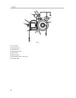


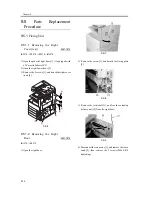


Chapter 9
9-10
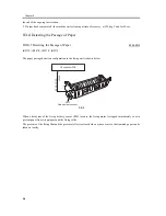
9.4.2
Detecting an Error
0006-6013
iR2270 / iR2870 / iR3570 / iR4570
As part of its protective mechanism, the machine checks for the following error conditions:
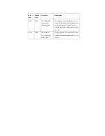
T-9-3
Error
code
Detail
code
Symptom
Description
E000
0000
The fixing
temperature fails to
increase.
In the course of start-up control, the
thermistor reading is less than 30 deg C 1
sec after the start of power supply or is
less than 70 deg C 2 sec after the start of
power supply; the machine will identify
an error condition if any of the foregoing
continues for 200 msec or more.
E001
0000
The thermistor
detects
overheating.
The thermistor detects 235 deg C for 200
msec or more continuously.
0001
A hardware circuit
detects
overheating.
A hardware circuit detects overheating in
relation to the thermistor (main or sub).
0002
The sub thermistor
detects
overheating.
The thermistor detects 295 deg C or more
for 200 msec or more continuously.
E002
0000
The fixing
temperature fails to
reach a specific
level.
In the course of start-up control, the
thermistor detects a temperature lower
then 115 deg C for 200 msec continuously
after it has detected 100 deg C; the
thermistor detects a temperature less than
150 deg C for 200 msec or more
continuously after it has detected 140 deg
C; or, the thermistor detects a temperature
lower than 165 deg C for 20 msec or more
continuously 1 sec after it has detected
160 deg C.
E003
0000
The fixing
temperature has
dropped to an
abnormally low
level.
In the course of normal temperature
control, the thermistor detects a
temperature lower than 140 deg C for 20
msec or more continuously.
Summary of Contents for iR4570 Series
Page 2: ...Download Free Service Manual And Resetter Printer at http printer1 blogspot com ...
Page 6: ...Download Free Service Manual And Resetter Printer at http printer1 blogspot com ...
Page 28: ...Download Free Service Manual And Resetter Printer at http printer1 blogspot com ...
Page 81: ...Chapter 2 Installation ...
Page 82: ......
Page 84: ......
Page 106: ...system setup network Ethernet driver setup auto detect ...
Page 126: ...F 2 94 3 2 3 1 ...
Page 127: ...Chapter 3 Basic Operation ...
Page 128: ......
Page 130: ......
Page 136: ......
Page 137: ...Chapter 4 Main Controller ...
Page 138: ......
Page 140: ......
Page 164: ......
Page 165: ...Chapter 5 Original Exposure System ...
Page 166: ......
Page 213: ...Chapter 6 Laser Exposure ...
Page 214: ......
Page 216: ......
Page 230: ......
Page 231: ...Chapter 7 Image Formation ...
Page 232: ......
Page 236: ......
Page 249: ...F 7 13 1 2 3 4 ...
Page 308: ......
Page 309: ...Chapter 8 Pickup Feeding System ...
Page 310: ......
Page 316: ......
Page 464: ......
Page 465: ...Chapter 9 Fixing System ...
Page 466: ......
Page 501: ...Chapter 10 External and Controls ...
Page 502: ......
Page 506: ......
Page 564: ......
Page 565: ...Chapter 11 MEAP ...
Page 566: ......
Page 568: ......
Page 573: ...Chapter 12 Maintenance and Inspection ...
Page 574: ......
Page 576: ......
Page 612: ......
Page 613: ...Chapter 13 Standards and Adjustments ...
Page 614: ......
Page 616: ......
Page 635: ...Chapter 14 Correcting Faulty Images ...
Page 636: ......
Page 675: ...T 14 22 Notation Description VR201 for factory use ...
Page 676: ......
Page 677: ...Chapter 15 Self Diagnosis ...
Page 678: ......
Page 680: ......
Page 757: ...Chapter 16 Service Mode ...
Page 758: ......
Page 760: ...Contents 16 8 1 COPIER 16 102 16 8 1 1 Copier List 16 102 ...
Page 869: ...Chapter 17 Service Tools ...
Page 870: ......
Page 871: ...Contents Contents 17 1 Special Tools 17 1 17 2 Oils and Solvents 17 2 ...
Page 872: ......
Page 875: ...Oct 8 2004 ...
Page 876: ......


