


Chapter 2
2-1
2.1
Making Pre-Checks
2.1.1
Selecting the Site of Installation
0007-4754
iR2270 / iR2870 / iR3570 / iR4570
Select the site of installation against the following requirements; if possible, visit the user's before delivery of the
machine:
1) There must be a power outlet properly grounded and rated as indicated (+, -10%) for exclusive use by the machine.
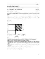
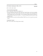
2) The environment of the room must be as indicated in the following diagram, and the machine must not be installed
near a water faucet, water boiler, humidifier, or refrigerator:
F-2-1
3) The machine must not be installed near a source of fire or in an area subject to dust or ammonium gas.
If the area is exposed to direct rays of the sun, provide curtains to the window.
4) The room must be well ventilated. (The level of ozone generated by the machine in use will not affect the
individuals around it. However, some may find its odor to be unpleasant, as when working in a poorly ventilated
room.)
5) The floor of the machine must be level so that the feet of the machine will remain in contact and the machine will
remain level.
6) The machine must be at least 10 cm away from any wall, permitting unobstructed use.
- Without a Finisher or Side Paper Deck-P1 Installed
Humidity (%RH)
80
60
40
20
10
0
10
15
20
27.5 30
(32)
(50)
(59)
(68)
(81.5)(86)
Temperature
75
25
Summary of Contents for iR4570 Series
Page 2: ...Download Free Service Manual And Resetter Printer at http printer1 blogspot com ...
Page 6: ...Download Free Service Manual And Resetter Printer at http printer1 blogspot com ...
Page 28: ...Download Free Service Manual And Resetter Printer at http printer1 blogspot com ...
Page 81: ...Chapter 2 Installation ...
Page 82: ......
Page 84: ......
Page 106: ...system setup network Ethernet driver setup auto detect ...
Page 126: ...F 2 94 3 2 3 1 ...
Page 127: ...Chapter 3 Basic Operation ...
Page 128: ......
Page 130: ......
Page 136: ......
Page 137: ...Chapter 4 Main Controller ...
Page 138: ......
Page 140: ......
Page 164: ......
Page 165: ...Chapter 5 Original Exposure System ...
Page 166: ......
Page 213: ...Chapter 6 Laser Exposure ...
Page 214: ......
Page 216: ......
Page 230: ......
Page 231: ...Chapter 7 Image Formation ...
Page 232: ......
Page 236: ......
Page 249: ...F 7 13 1 2 3 4 ...
Page 308: ......
Page 309: ...Chapter 8 Pickup Feeding System ...
Page 310: ......
Page 316: ......
Page 464: ......
Page 465: ...Chapter 9 Fixing System ...
Page 466: ......
Page 501: ...Chapter 10 External and Controls ...
Page 502: ......
Page 506: ......
Page 564: ......
Page 565: ...Chapter 11 MEAP ...
Page 566: ......
Page 568: ......
Page 573: ...Chapter 12 Maintenance and Inspection ...
Page 574: ......
Page 576: ......
Page 612: ......
Page 613: ...Chapter 13 Standards and Adjustments ...
Page 614: ......
Page 616: ......
Page 635: ...Chapter 14 Correcting Faulty Images ...
Page 636: ......
Page 675: ...T 14 22 Notation Description VR201 for factory use ...
Page 676: ......
Page 677: ...Chapter 15 Self Diagnosis ...
Page 678: ......
Page 680: ......
Page 757: ...Chapter 16 Service Mode ...
Page 758: ......
Page 760: ...Contents 16 8 1 COPIER 16 102 16 8 1 1 Copier List 16 102 ...
Page 869: ...Chapter 17 Service Tools ...
Page 870: ......
Page 871: ...Contents Contents 17 1 Special Tools 17 1 17 2 Oils and Solvents 17 2 ...
Page 872: ......
Page 875: ...Oct 8 2004 ...
Page 876: ......


