


Chapter 8
8-34
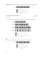
8.5
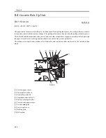
Manual Feed Pickup Unit
8.5.1
Overview
0007-2123
iR2270 / iR2870 / iR3570 / iR4570
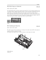
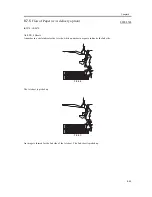
The paper in the tray of the manual feed pickup unit is forced against the manual feed pickup roller by the work of
the pickup guide plate; the manual feed pickup roller and the separation pad serve to make sure that only a single
sheet of paper is separated and moved into the machine:
(1) the pickup guide plate is locked in place at all times, and does not require drive for pickup operation.
(2) multi-pickup roller is driven by the main motor (M2) through the manual feed pickup clutch (CL1).
F-8-29
[1] Upper guide
[2] Stopper plate
[3] Side guide
[4] Manual feed pickup tray
[5] Pressure spring
[6] Holding plate
[7] Manual feed paper sensor flag
[8] Separation pad
[9] Manual feed pickup roller
[10] (to registration roller assembly)
REF
The machine's manual feed pickup unit is not equipped with a sensor that may detect the last sheet of paper.
[1]
[2]
[3]
[4]
[5]
[6]
[7]
[8]
[9]
[10]
Summary of Contents for iR4570 Series
Page 2: ...Download Free Service Manual And Resetter Printer at http printer1 blogspot com ...
Page 6: ...Download Free Service Manual And Resetter Printer at http printer1 blogspot com ...
Page 28: ...Download Free Service Manual And Resetter Printer at http printer1 blogspot com ...
Page 81: ...Chapter 2 Installation ...
Page 82: ......
Page 84: ......
Page 106: ...system setup network Ethernet driver setup auto detect ...
Page 126: ...F 2 94 3 2 3 1 ...
Page 127: ...Chapter 3 Basic Operation ...
Page 128: ......
Page 130: ......
Page 136: ......
Page 137: ...Chapter 4 Main Controller ...
Page 138: ......
Page 140: ......
Page 164: ......
Page 165: ...Chapter 5 Original Exposure System ...
Page 166: ......
Page 213: ...Chapter 6 Laser Exposure ...
Page 214: ......
Page 216: ......
Page 230: ......
Page 231: ...Chapter 7 Image Formation ...
Page 232: ......
Page 236: ......
Page 249: ...F 7 13 1 2 3 4 ...
Page 308: ......
Page 309: ...Chapter 8 Pickup Feeding System ...
Page 310: ......
Page 316: ......
Page 464: ......
Page 465: ...Chapter 9 Fixing System ...
Page 466: ......
Page 501: ...Chapter 10 External and Controls ...
Page 502: ......
Page 506: ......
Page 564: ......
Page 565: ...Chapter 11 MEAP ...
Page 566: ......
Page 568: ......
Page 573: ...Chapter 12 Maintenance and Inspection ...
Page 574: ......
Page 576: ......
Page 612: ......
Page 613: ...Chapter 13 Standards and Adjustments ...
Page 614: ......
Page 616: ......
Page 635: ...Chapter 14 Correcting Faulty Images ...
Page 636: ......
Page 675: ...T 14 22 Notation Description VR201 for factory use ...
Page 676: ......
Page 677: ...Chapter 15 Self Diagnosis ...
Page 678: ......
Page 680: ......
Page 757: ...Chapter 16 Service Mode ...
Page 758: ......
Page 760: ...Contents 16 8 1 COPIER 16 102 16 8 1 1 Copier List 16 102 ...
Page 869: ...Chapter 17 Service Tools ...
Page 870: ......
Page 871: ...Contents Contents 17 1 Special Tools 17 1 17 2 Oils and Solvents 17 2 ...
Page 872: ......
Page 875: ...Oct 8 2004 ...
Page 876: ......


