


Chapter 12
12-8
The foregoing values are estimates only, and are subject to change depending on future data.
12.3.3
Scheduled Servicing Basic Procedures
0007-5173
iR2270 / iR2870 / iR3570 / iR4570
- As a rule, perform scheduled servicing every 120,000 prints.
- Before setting out on a scheduled visit, check with the Service Book, and take parts for which replacement is
expected.
- If the power plug is exposed to dust, humidity, or oily smoke, the resulting buildup can prove to be a fire hazard.
(The buildup of dust, for instance, can absorb moisture and suffer insulating failure.) Be sure to disconnect the power
plug on a periodical basis, and remove any buildup of dust and dirt with a dry cloth.
<Work Procedure>
1) Report to the person in change, and have an understanding of the situation.
2) Record the counter reading, and check the faulty prints.
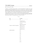
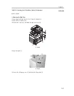
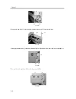
3) Check the following items, and adjust or clean the parts as needed.
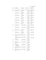
Laser
scan
ner
asse
mbly
Location
Dust-blocking glass
Task
clean:(dry wiping or alcohol)
Interval
120,000 prints
Remarks
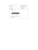
[1]Dust-blocking glass
Summary of Contents for iR4570 Series
Page 2: ...Download Free Service Manual And Resetter Printer at http printer1 blogspot com ...
Page 6: ...Download Free Service Manual And Resetter Printer at http printer1 blogspot com ...
Page 28: ...Download Free Service Manual And Resetter Printer at http printer1 blogspot com ...
Page 81: ...Chapter 2 Installation ...
Page 82: ......
Page 84: ......
Page 106: ...system setup network Ethernet driver setup auto detect ...
Page 126: ...F 2 94 3 2 3 1 ...
Page 127: ...Chapter 3 Basic Operation ...
Page 128: ......
Page 130: ......
Page 136: ......
Page 137: ...Chapter 4 Main Controller ...
Page 138: ......
Page 140: ......
Page 164: ......
Page 165: ...Chapter 5 Original Exposure System ...
Page 166: ......
Page 213: ...Chapter 6 Laser Exposure ...
Page 214: ......
Page 216: ......
Page 230: ......
Page 231: ...Chapter 7 Image Formation ...
Page 232: ......
Page 236: ......
Page 249: ...F 7 13 1 2 3 4 ...
Page 308: ......
Page 309: ...Chapter 8 Pickup Feeding System ...
Page 310: ......
Page 316: ......
Page 464: ......
Page 465: ...Chapter 9 Fixing System ...
Page 466: ......
Page 501: ...Chapter 10 External and Controls ...
Page 502: ......
Page 506: ......
Page 564: ......
Page 565: ...Chapter 11 MEAP ...
Page 566: ......
Page 568: ......
Page 573: ...Chapter 12 Maintenance and Inspection ...
Page 574: ......
Page 576: ......
Page 612: ......
Page 613: ...Chapter 13 Standards and Adjustments ...
Page 614: ......
Page 616: ......
Page 635: ...Chapter 14 Correcting Faulty Images ...
Page 636: ......
Page 675: ...T 14 22 Notation Description VR201 for factory use ...
Page 676: ......
Page 677: ...Chapter 15 Self Diagnosis ...
Page 678: ......
Page 680: ......
Page 757: ...Chapter 16 Service Mode ...
Page 758: ......
Page 760: ...Contents 16 8 1 COPIER 16 102 16 8 1 1 Copier List 16 102 ...
Page 869: ...Chapter 17 Service Tools ...
Page 870: ......
Page 871: ...Contents Contents 17 1 Special Tools 17 1 17 2 Oils and Solvents 17 2 ...
Page 872: ......
Page 875: ...Oct 8 2004 ...
Page 876: ......


