


CHAPTER 8 EXTERNALS AND AUXILIARY CONTROL SYSTEM
COPYRIGHT© 2002 CANON INC.
2000
CANON iR1600/iR2000/iR1610/iR2010 SERIES REV.0 MAR. 2002
8-25
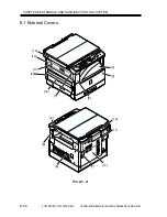
6.4 Fan
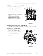
6.4.1 Removing the Heat Discharge Fan
1) Remove the rear cover.
2) Remove the printer board unit. (if
equipped with printer functions; see
6.5.11)
3) Disconnect the connector [1].
4) Remove the 4 screws [2], and detach the
heat discharge fan assembly [3].
F08-604-01
5) Remove the 2 screws [4], and detach the
heat discharge fan [5].
F08-604-02
When mounting the heat dis-
charge fan, be sure to match the
arrow [6] indicating the direc-
tion of air current and the arrow
[7] on the hood.
F08-604-03
[1]
[3]
[2]
[2]
[2]
[5]
[4]
[7]
[6]
Summary of Contents for iR1600 Series
Page 24: ......
Page 26: ......
Page 96: ......
Page 110: ......
Page 112: ......
Page 144: ......
Page 146: ......
Page 158: ......
Page 160: ......
Page 182: ......
Page 216: ......
Page 218: ......
Page 248: ......
Page 250: ......
Page 284: ......
Page 298: ......
Page 300: ......
Page 312: ......
Page 314: ......
Page 366: ......
Page 368: ......
Page 378: ......
Page 604: ......
Page 606: ......
Page 648: ......
Page 650: ......
Page 652: ......
Page 656: ......
Page 660: ......
Page 665: ...COPYRIGHT 2002 CANON INC CANON FAX BOARD REV 0 MAR 2002 CHAPTER 1 INTRODUCTION...
Page 666: ......
Page 671: ...COPYRIGHT 2002 CANON INC CANON FAX BOARD REV 0 MAR 2002 CHAPTER 2 BASIC OPERATION...
Page 672: ......
Page 679: ...COPYRIGHT 2002 CANON INC CANON FAX BOARD REV 0 MAR 2002 CHAPTER 3 TROUBLESHOOTING...
Page 680: ......
Page 688: ......
Page 694: ......
Page 696: ......
Page 702: ......
Page 704: ......
Page 712: ......
Page 722: ......
Page 732: ......
Page 734: ......
Page 736: ......


