CHAPTER 3 IMAGE READING/PROCESSING SYSTEM
COPYRIGHT© 2002 CANON INC.
2000
CANON iR1600/iR2000/iR1610/iR2010 SERIES REV.0 MAR. 2002
3 - 2
2 Reader Drive System
2.1 Outline
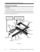
The reader drive system consists of the following: reader motor, drive pulley, carriage,
carriage rail, carriage drive belt.
The drive signal from the image processor PCB is sent to the reader motor (M103) by
way of the driver circuit on the original detention/reader motor drive PCB. The drive from
the reader motor is transmitted to the carriage by way of the drive pulley and drive belt to
move the carriage forward or in reverse.
F03-201-01
Carriage rail
Drive pulleys
Reader motor
(M103)
(forward)
(reverse)
Image processor
PCB
Original detection/reader
motor drive PCB
Drive belt
Spacer
Spacer
Analog
processor
PCB
Carriage drive belt
Drive pulley
Drive pulley
Carriage
CS unit HP sensor
(PS113)
Contact sensor
unit
Sensor
light-blocking
plate
Summary of Contents for iR1600 Series
Page 24: ......
Page 26: ......
Page 96: ......
Page 110: ......
Page 112: ......
Page 144: ......
Page 146: ......
Page 158: ......
Page 160: ......
Page 182: ......
Page 216: ......
Page 218: ......
Page 248: ......
Page 250: ......
Page 284: ......
Page 298: ......
Page 300: ......
Page 312: ......
Page 314: ......
Page 366: ......
Page 368: ......
Page 378: ......
Page 604: ......
Page 606: ......
Page 648: ......
Page 650: ......
Page 652: ......
Page 656: ......
Page 660: ......
Page 665: ...COPYRIGHT 2002 CANON INC CANON FAX BOARD REV 0 MAR 2002 CHAPTER 1 INTRODUCTION...
Page 666: ......
Page 671: ...COPYRIGHT 2002 CANON INC CANON FAX BOARD REV 0 MAR 2002 CHAPTER 2 BASIC OPERATION...
Page 672: ......
Page 679: ...COPYRIGHT 2002 CANON INC CANON FAX BOARD REV 0 MAR 2002 CHAPTER 3 TROUBLESHOOTING...
Page 680: ......
Page 688: ......
Page 694: ......
Page 696: ......
Page 702: ......
Page 704: ......
Page 712: ......
Page 722: ......
Page 732: ......
Page 734: ......
Page 736: ......


