


CHAPTER 5 IMAGE FORMATION SYSTEM
COPYRIGHT© 2002 CANON INC.
2000
CANON iR1600/iR2000/iR1610/iR2010 SERIES REV.0 MAR. 2002
5-19
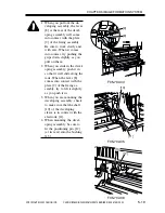
1. When you pull out the de-
veloping assembly, the lever
[8] at the rear of the devel-
oping assembly will come
into contact with the plate
[9] of the fixing assembly.
Be sure to work slowly and
with care. When it comes
into contact, try pushing the
grips down slightly as you
pull on them.
2. When you slide in the devel-
oping assembly, push it in
so that it will slide along the
rails. When the lever [8]
comes into contact with the
plate [9] of the fixing as-
sembly, try to lift it slightly
as you push it in.
3. When you are mounting the
developing assembly, check
to make sure that the shaft
[10] of the developing
sleeve is in contact with the
electrode [11].
4. When mounting the devel-
oping assembly, be sure to
fit the positioning pin [12]
(at its rear) into the bushing
[13].
F05-702-05
F05-702-04
F05-702-06
[9]
[8]
[11]
[10]
[13]
[12]
Summary of Contents for iR1600 Series
Page 24: ......
Page 26: ......
Page 96: ......
Page 110: ......
Page 112: ......
Page 144: ......
Page 146: ......
Page 158: ......
Page 160: ......
Page 182: ......
Page 216: ......
Page 218: ......
Page 248: ......
Page 250: ......
Page 284: ......
Page 298: ......
Page 300: ......
Page 312: ......
Page 314: ......
Page 366: ......
Page 368: ......
Page 378: ......
Page 604: ......
Page 606: ......
Page 648: ......
Page 650: ......
Page 652: ......
Page 656: ......
Page 660: ......
Page 665: ...COPYRIGHT 2002 CANON INC CANON FAX BOARD REV 0 MAR 2002 CHAPTER 1 INTRODUCTION...
Page 666: ......
Page 671: ...COPYRIGHT 2002 CANON INC CANON FAX BOARD REV 0 MAR 2002 CHAPTER 2 BASIC OPERATION...
Page 672: ......
Page 679: ...COPYRIGHT 2002 CANON INC CANON FAX BOARD REV 0 MAR 2002 CHAPTER 3 TROUBLESHOOTING...
Page 680: ......
Page 688: ......
Page 694: ......
Page 696: ......
Page 702: ......
Page 704: ......
Page 712: ......
Page 722: ......
Page 732: ......
Page 734: ......
Page 736: ......