CHAPTER 7 FIXING SYSTEM
COPYRIGHT© 2002 CANON INC.
2000
CANON iR1600/iR2000/iR1610/iR2010 SERIES REV.0 MAR. 2002
7-20
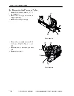
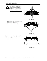
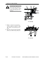
13) Push down the pressure releasing lever
to lock it in place.
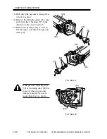
14) Remove the left/right spring [26]; then,
push down the 2 bushings [27] in the
direction of the arrow to detach.
15) Remove the bearings [28] (2 each on
left and right), and detach the pressure
roller [29].
F07-304-11
If the pressure releasing lever
[30] or the fixing shaft [31] has
come off when the pressure
roller is removed, be sure to
mount them back as shown.
F07-304-12
[26]
[29]
[27]
[28]
[26]
[29]
[27]
[28]
[30]
[31]
Summary of Contents for iR1600 Series
Page 24: ......
Page 26: ......
Page 96: ......
Page 110: ......
Page 112: ......
Page 144: ......
Page 146: ......
Page 158: ......
Page 160: ......
Page 182: ......
Page 216: ......
Page 218: ......
Page 248: ......
Page 250: ......
Page 284: ......
Page 298: ......
Page 300: ......
Page 312: ......
Page 314: ......
Page 366: ......
Page 368: ......
Page 378: ......
Page 604: ......
Page 606: ......
Page 648: ......
Page 650: ......
Page 652: ......
Page 656: ......
Page 660: ......
Page 665: ...COPYRIGHT 2002 CANON INC CANON FAX BOARD REV 0 MAR 2002 CHAPTER 1 INTRODUCTION...
Page 666: ......
Page 671: ...COPYRIGHT 2002 CANON INC CANON FAX BOARD REV 0 MAR 2002 CHAPTER 2 BASIC OPERATION...
Page 672: ......
Page 679: ...COPYRIGHT 2002 CANON INC CANON FAX BOARD REV 0 MAR 2002 CHAPTER 3 TROUBLESHOOTING...
Page 680: ......
Page 688: ......
Page 694: ......
Page 696: ......
Page 702: ......
Page 704: ......
Page 712: ......
Page 722: ......
Page 732: ......
Page 734: ......
Page 736: ......

