


CHAPTER 11 INSTALLATION
COPYRIGHT© 2002 CANON INC.
2000
CANON iR1600/iR2000/iR1610/iR2010 SERIES REV.0 MAR. 2002
11-43
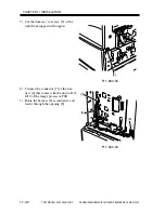
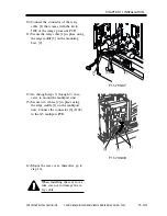
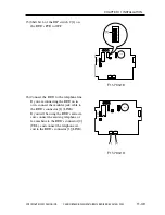
10) Connect the connector of the relay
cable [1] that comes with the kit to
J208 of the image processor PCB.
11) Secure the relay cable [1] in place using
the edge saddle [3] on the mounting
base [2].
F11-703-07
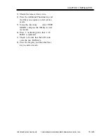
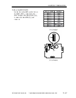
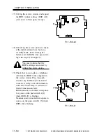
12) Go through steps 5) through 9) in re-
verse to mount the multiport unit.
13) Secure two cables [2] in place using
the edge saddle [1] on the multiport
unit. Connect the connector [3] (J104)
to the G3 multiport PCB.
F11-703-08
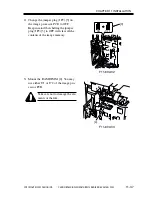
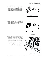
14) Mount the rear cover; thereafter, go to
step 16).
When installing the rear cover,
take care not to damage the re-
lay cable.
[1]
[2]
[3]
[3]
[1]
[2]
Summary of Contents for iR1600 Series
Page 24: ......
Page 26: ......
Page 96: ......
Page 110: ......
Page 112: ......
Page 144: ......
Page 146: ......
Page 158: ......
Page 160: ......
Page 182: ......
Page 216: ......
Page 218: ......
Page 248: ......
Page 250: ......
Page 284: ......
Page 298: ......
Page 300: ......
Page 312: ......
Page 314: ......
Page 366: ......
Page 368: ......
Page 378: ......
Page 604: ......
Page 606: ......
Page 648: ......
Page 650: ......
Page 652: ......
Page 656: ......
Page 660: ......
Page 665: ...COPYRIGHT 2002 CANON INC CANON FAX BOARD REV 0 MAR 2002 CHAPTER 1 INTRODUCTION...
Page 666: ......
Page 671: ...COPYRIGHT 2002 CANON INC CANON FAX BOARD REV 0 MAR 2002 CHAPTER 2 BASIC OPERATION...
Page 672: ......
Page 679: ...COPYRIGHT 2002 CANON INC CANON FAX BOARD REV 0 MAR 2002 CHAPTER 3 TROUBLESHOOTING...
Page 680: ......
Page 688: ......
Page 694: ......
Page 696: ......
Page 702: ......
Page 704: ......
Page 712: ......
Page 722: ......
Page 732: ......
Page 734: ......
Page 736: ......


