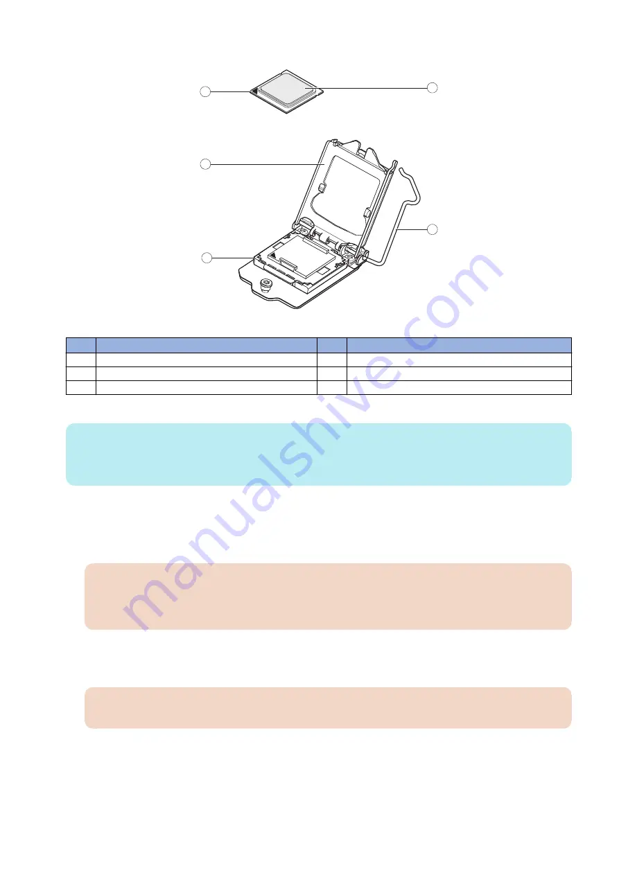
7. Open the load plate (see below figure).
5
4
1
3
2
Figure 20: Removing/replacing the CPU
No.
Item
No.
Item
1
Yellow triangle
4
CPU
2
Load plate open
5
Socket lever in the open position
3
Flat corner of socket border
8. Grasp the CPU by its edges, lift it out of the socket, and then place the CPU in a safe place.
NOTE:
If you remove the CPU from the motherboard to install it on a new motherboard, unpack the new motherboard and remove
the protective plastic cover from the CPU socket. Transfer the protective cover to the CPU socket of the old motherboard to
protect the circuitry.
● To replace a CPU
1. Do one of the following:
• If you are installing a new CPU cooling assembly on an existing CPU, clean the contact surface of the CPU to remove
any old thermal compound residue. A thermal pad is preinstalled on the underside of the new CPU cooling assembly.
IMPORTANT:
Be sure to remove all thermal compound residue from the surface of the CPU. It may help to scrape all the residue
off the surface using the flat edge of a nonconductive tool. Then use a lint-free cloth moistened with alcohol to
clean the surface.
• If you are installing the existing CPU and CPU cooling assembly on a new motherboard, clean the contact surfaces of
the CPU and cooling assembly as described earlier. Then apply fresh thermal compound to the contact surface of the
CPU using the applicator provided with the new motherboard.
IMPORTANT:
To apply a fresh thermal compound, use ShinEtsu PCS-TC-11T-13 thermal pad.
2. Prepare the CPU socket by ensuring that:
• The socket lever is in the open position.
• The load plate is open.
3. Place the CPU in the socket (see
).
The CPU and the socket are keyed to ensure correct installation. The two notches on the edges of the CPU correspond with
the two small posts inside the socket. Align the two notches properly with the two small posts.
Align the yellow triangle on the CPU with the flat corner of the socket. Do not force the CPU.
3. REPLACING PARTS
30
Summary of Contents for imagePASS-P2
Page 1: ...Revision 1 1 imagePASS P2 Service Manual ...
Page 6: ...Introduction 1 Introduction 2 Specifications 6 ...
Page 13: ...Using the imagePASS 2 Using the imagePASS 9 ...
Page 16: ...Figure 3b The imagePASS Tools menu 2 Using the imagePASS 11 ...
Page 17: ...REPLACING PARTS 3 Replacing Parts 13 ...
Page 44: ...INSTALLING SYSTEM SOFTWARE 4 Installing System Software 40 ...


