4. Select Fiery Server > Regional Settings and specify the current date and time, and click Save.
5. Click Log Out to exit Configure.
● Motherboard jumpers
IMPORTANT:
Jumper configuration should not be changed.
Jumper
Description
J17
Pin 1
J17 is the Clear CMOS and Password jumper.
Default configuration: jumper cap installed on pins 2 and 3.
NOTE:
Because the jumper cap is very small, it is not necessary—and could introduce an error—to
remove the jumper cap in order to clear the CMOS settings.
14
MS
MS
1
12
16
MS
MS
MS
15
13
3
4
5
6
8
9
2
11
MS
7
10
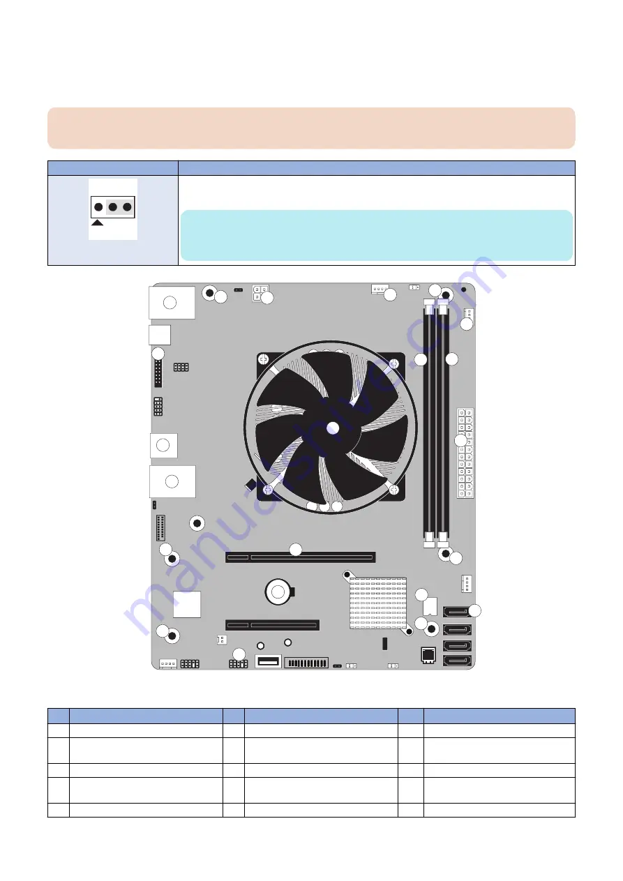
Figure 13: Diagram of the motherboard
No.
Item
No.
Item
No.
Item
1
HDD data connector (SATA0)
7
DIMM-B0
13
4-pin power connector (PWRCONN1)
2
Security chip (J23)
8
Crossover Ethernet port / Type A
USB3.0 ports (x2)
14
CPU fan connector (CPU FAN J16)
3
Battery (CR1)
9
Type A USB2.0 connector (x2)
15
FRONT FAN connector (J30)
4
Printer interface board (PCIE x16)
10
Type A USB2.0 ports (x2) / Network
port (RJ-45)
16
Service board connector (Port 80
Header) (EFI GPIO Header, J4)
5
Power button pins (J11)
11
CPU and cooling assembly
MS
Mounting screws
3. REPLACING PARTS
23
Summary of Contents for imagePASS-P2
Page 1: ...Revision 1 1 imagePASS P2 Service Manual ...
Page 6: ...Introduction 1 Introduction 2 Specifications 6 ...
Page 13: ...Using the imagePASS 2 Using the imagePASS 9 ...
Page 16: ...Figure 3b The imagePASS Tools menu 2 Using the imagePASS 11 ...
Page 17: ...REPLACING PARTS 3 Replacing Parts 13 ...
Page 44: ...INSTALLING SYSTEM SOFTWARE 4 Installing System Software 40 ...


