4. Close the load plate.
5. Lower the socket lever and place it in the locked position under the retention post.
6. Prepare the CPU cooling assembly for installation.
• Make sure that the motherboard is placed on a padded, antistatic work surface.
• Apply the fresh thermal compound square, as described in step 1 on page 38.
• Align the cooling assembly so that when it is installed, the fan cable easily reaches the CPU fan power connector CPU
FAN on the motherboard.
7. Place the cooling assembly on the CPU.
• Make sure that the thermal pad on the underside of the heatsink is positioned on top of the CPU.
CAUTION:
Be sure to remove any protective material that may be covering the surface of the thermal pad. Otherwise, the
CPU may overheat.
• Align the four screws with the four screw posts.
• Tighten the screws. Partially tighten all the screws before tightening any one screw all the way.
8. Connect the CPU fan cable to the motherboard connector CPU FAN.
The cable connector is keyed to fit only one way. Make sure that the connector on the cable is securely attached to connector
CPU FAN on the motherboard.
9. Install the motherboard in the chassis (see
“To replace the motherboard” on page 27
).
10. Replace the motherboard components (see
“To replace motherboard components” on page 28
).
11. Reassemble the imagePASS and verify its functionality (see
“To reinstall and verify the imagePASS” on page 38
).
12. If you installed a new CPU, configure the time and date in Setup (see
“To configure the system date and time” on page 22
■ Service board
The service board contains the LED display and service switches.
● To remove the service board
1. Access and open the imagePASS, as described on
“Accessing the imagePASS” on page 16
.
2. Disconnect the service board cable from the service board and motherboard.
3. If you are replacing the service board cable, remove the cable from the plastic clips that secure it to the chassis.
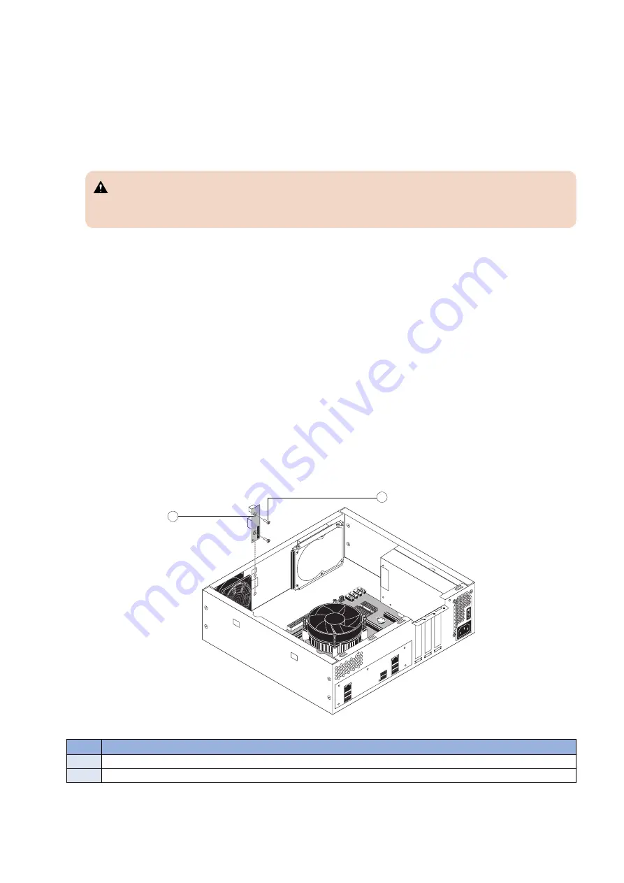
4. Remove the two screws that secure the service board to the chassis, and remove the board from the chassis (see below
figure).
1
2
Figure 21: Removing/replacing the service board
No.
Item
1
Service board
2
Screw (1 of 2)
● To replace the service board
1. If you are replacing the old service board with a new one, unpack the new board and cable.
3. REPLACING PARTS
31
Summary of Contents for imagePASS-P2
Page 1: ...Revision 1 1 imagePASS P2 Service Manual ...
Page 6: ...Introduction 1 Introduction 2 Specifications 6 ...
Page 13: ...Using the imagePASS 2 Using the imagePASS 9 ...
Page 16: ...Figure 3b The imagePASS Tools menu 2 Using the imagePASS 11 ...
Page 17: ...REPLACING PARTS 3 Replacing Parts 13 ...
Page 44: ...INSTALLING SYSTEM SOFTWARE 4 Installing System Software 40 ...


