■ Replacing the motherboard
Use the following procedure to install the motherboard in the imagePASS chassis.
● To replace the motherboard
1. If you are installing a new motherboard, do the following:
• Remove the security chip from the old motherboard and install it onto the new motherboard(see
• Install the DIMM(s) from the old motherboard onto the new motherboard(see
).
• Install the CPU from the old motherboard onto the new motherboard(see
“CPU and CPU cooling assembly” on page
).
When installing these components, make sure that the motherboard is placed on an antistatic surface with some padding.
Do not transfer the BIOS chip from the old motherboard onto the new motherboard. Doing so can cause the system to shut
down due to incompatibility issues.
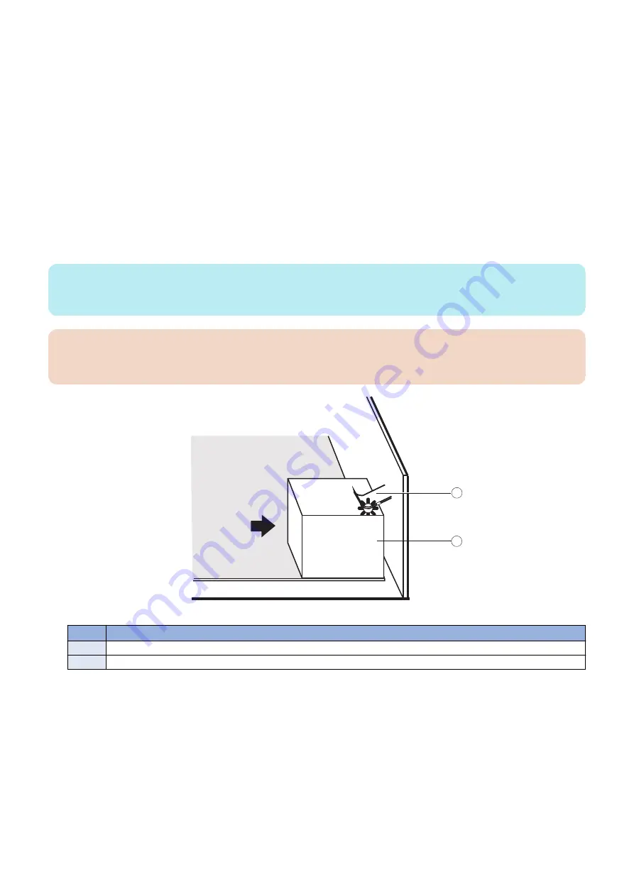
2. Angle the motherboard so that the connectors on the motherboard fit into the cutouts in the connector panel of
the chassis, and gently slide the motherboard into the chassis (see
“To remove the motherboard” on page 24
NOTE:
As you slide the motherboard into position, lift the connector edge to ensure that the underside of jumper area PCIEX8 clears the
nearby screw standoff.
IMPORTANT:
Be sure to fit the motherboard Ethernet connectors under the metal grounding tabs in the cutouts. Failure to position the
grounding tabs correctly may result in permanent damage to the motherboard and power supply.
1
2
Figure 17: Fitting the connectors under the metal grounding tab
No.
Item
1
Metal grounding tab
2
Motherboard connector
3. Align the mounting holes on the motherboard with the screw holes located in the base of the chassis (see
4. Insert the six mounting screws that attach the motherboard to the chassis.
Partially tighten each screw before completely tightening any one screw. Do not overtighten the screws; doing so could
damage traces on the motherboard.
Now you are ready to replace the remaining motherboard components to complete the motherboard installation.
3. REPLACING PARTS
27
Summary of Contents for imagePASS-P2
Page 1: ...Revision 1 1 imagePASS P2 Service Manual ...
Page 6: ...Introduction 1 Introduction 2 Specifications 6 ...
Page 13: ...Using the imagePASS 2 Using the imagePASS 9 ...
Page 16: ...Figure 3b The imagePASS Tools menu 2 Using the imagePASS 11 ...
Page 17: ...REPLACING PARTS 3 Replacing Parts 13 ...
Page 44: ...INSTALLING SYSTEM SOFTWARE 4 Installing System Software 40 ...


