4. Repair Guide
- 21 -
5.2 PCA-XIF board firmware recovery
5.2.1 Introduction
It is possible for the firmware in the normal area to be erased or damaged if the updating has
failed because a communication error occurred while the normal area firmware was being
updated or because the power of the X-ray interface box was turned off.
If the normal area firmware has been erased, the backup code body can be booted by the backup
code initializing routine when the power is turned off and then back on so the firmware can be
updated again.
However, if the normal area firmware has been damaged, the backup code body will not be
booted simply by turning the power off and then back on, and it will be necessary to forcibly
boot the backup codes.
This section describes how to perform the forced backup booting operation and also the
precautions to be heeded.
5.2.2 Forced backup boot operation
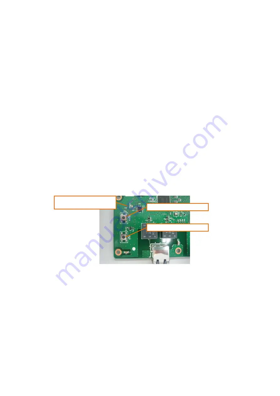
If the normal area firmware has been damaged, the firmware in the backup area can be forcibly
booted by operating the switches on the board. The operations undertaken for forced backup
booting are described below.
1) Start pressing the RESET switch and BOOTSEL switch on the PCA-XIF board at the same
time.
2) With the BOOTSEL switch still held down, release the RESET switch first.
3) Wait for one second, and then release the BOOTSEL switch.
When the firmware has been booted as a result of taking the steps above, the IP address and
MAC address are set to the default values.
[Default settings]
IP address
:
192.168.100.96
Subnet mask
:
255.255.255.0
Default gateway
:
0.0.0.0
MAC address
:
00:1E:8F:CA:87:80
* Since the IP address and MAC address (separate values different from 00:1E:8F:CA:87:80)
written in the flash memory are displayed as the IP address and MAC address indicated in the
network settings on the Status View screen for the Web browser, the default values will not be
displayed even if forced backup start is implemented.
* Even after forced backup start has been implemented, the original IP address and separate
MAC address are stored on the flash memory so the original addresses will be restored when
normal start is initiated.
SW1 (RESET switch)
SW2 (BOOTSEL switch)
The STATUS LED blinks
during backup booting.
Summary of Contents for CXDI-80C
Page 6: ...Note These measurements are only guidelines ...
Page 10: ...1 1 O Ov ve er rv vi ie ew w 2 2 System diagram ...
Page 48: ...2 Installation procedures 15 4 Handle unit option Corner pads Outer box Inner box ...
Page 133: ...Rev 01 CONTENTS Detector unit 1 X ray interface box unit 2 Wiring unit 4 Handle unit 6 ...


