46
Electrical installation
Type 8792, 8793 REV.2
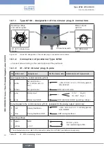
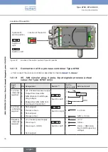
Location of the switch:
Symbols for
switch position
Location of the switch
Switch on left
Switch on
right
Figure 22:
Location of the switch; symbols for switch position
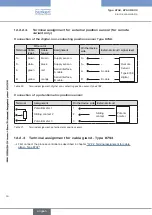
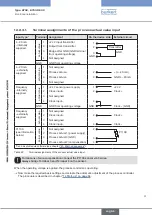
12.1.5 Connection of the process controller Type 8793
→
First connect the process controller as described in chapter “12.1.2” to “12.1.4”.
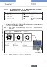
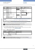
12.1.6 X5 - M8 circular plug, 4-pole, input signals process actual
value (for Type 8793 only)
Input
type*
Pin Assignment
Switch ***
On the
device side External circuit
4...20 mA
- internally
supplied
1
+24 V transmitter power supply
Switch on left
GND
1
2
3
4
Transmitter
I
2
Output from transmitter
3
GND (identical to GND oper-
ating voltage)
4
Bridge after GND (GND from
3-conductor transmitter)
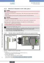
4...20 mA
- externally
supplied
1
Not assigned
Switch on right
2
Process
2
4...20 mA
3
Not assigned
4
Process actual -
4
GND 4...20 mA
Frequency
- internally
supplied
1
+24 V sensor power supply
Switch on left
1
+24 V
2
Clock input +
2
Clock +
3
Clock input – (GND)
3
Clock – / GND (iden-
tical to GND operating
voltage)
4
Not assigned
english
Summary of Contents for 8792
Page 196: ...www burkert com ...

