


171
büS option
Type 8792, 8793 REV.2
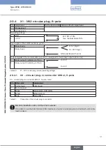
20.4 X1 - M12 circular plug, 8-pole
Pin Assignment
On the device side External circuit / signal level
1
Not assigned
2
Not assigned
Operating voltage
3
GND
24 V DC ± 10%
max. residual ripple 10%
3
4
4
+ 24 V
Input signal of the control center (e.g. PLC)
5
Binary input +
0...5 V (log.0)
10...30 V (log.1)
GND (identical with pin 3)
+
5
6
6
Binary input -
Output signals to the control center (e.g. PLC) - (assigned for the binary output option only)
7
Binary output 1 (referring to Pin 3)
8
7
0...24 V
0...24 V
8
Binary output 2 (referring to Pin 3)
Table 60:
X1 - M12 circular plug, 8-pole (operating voltage)
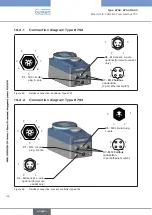
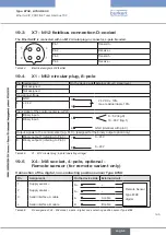
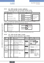
20.4.1 X3 - circular plug-in connector M12x1, 5-pole
X3 - circular plug-in connector M12x1, 5-pole, male:
Pin
Wire color
Assignment
1
CAN shield
CAN shield
2
Not assigned
3
Black
Black GND / CAN_GND
4
White
White CAN_H
5
Blue
Blue CAN_L
Table 61:
Connection of the circular plug-in connector
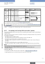
Electrical installation with or without büS network:
To be able to use the büS network (CAN interface), a 5-pole circular plug and a shielded 5-wire cable
must be used.
english
Summary of Contents for 8792
Page 196: ...www burkert com ...


