X90 mobile modules
64
X90 mobile system User's manual V 1.20 - Translation of the original manual
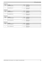
The output information is always used by the main output and all outputs connected in parallel. A maximum of
4 adjacent outputs are permitted to be connected in parallel on the outputs (1 main output, 3 parallel outputs).
Parallel connections are not possible via inputs.
Data type
Values
Information
0
Off (default)
1
Digital main output
10
Digital PWM main output
20
Digital parallel output
31
Digital input in source configuration with 9 kΩ input resistance
USINT
41
Digital input in sink configuration with 9 kΩ input resistance
5.2.1.12.5 Digital inputs
The module is equipped with 48 digital inputs for 1-wire connections. The inputs of the module are designed for
sink and source circuits.
Topics in this section:
•
Filter time
•
Threshold value / Hysteresis
•
Input values of the digital inputs
Not all options are available for an input. The threshold value and hysteresis are only available for inputs 9 to 24,
for example, since an analog procedure is used for measurement here.
Input impedance is tightly defined by the physical configuration.
5.2.1.12.5.1 Digital input filter
Name:
cfgDigitalFilter01 to cfgDigitalFilter08
cfgDigitalFilter09 to cfgDigitalFilter24
cfgDigitalFilter25 to cfgDigitalFilter32
cfgDigitalFilter33 to cfgDigitalFilter48
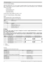
This register can be used to specify the filter value for all digital inputs in steps of 100 μs. The filter is implemented
as a ramp filter.
Data type
Values
Information
0
No software filter
1
0.1 ms
...
10
1 ms (default)
...
USINT
250
25 ms - Higher values are limited to this value.
Input
signal
Signal after
the filter
t
Delay
t
Delay
t
Delay
t
Delay
Time
Time
⇒ Input delay


