X90 mobile modules
X90 mobile system User's manual V 1.20 - Translation of the original manual
47
5.2.1.5.8.2 CAN bus interface
IF7, IF8, IF9 - CAN bus
CAN1
CAN2
CAN3
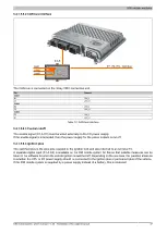
The CAN bus is connected on the 3-bay CMC connection unit.
Pin
Channel
CAN1
B1
CAN_L
C1
CAN_H
CAN2
B2
CAN_L
C2
CAN_H
CAN3
D1
CAN_L
E1
CAN_H
Table 12: CAN bus interface
5.2.1.5.8.3 Central cutoff
The enable signal (X1.A.C3) must be wired externally to the I/O power supply.
If the enable signal is interrupted, then the power supply for the power outputs is cut off.
5.2.1.5.8.4 Ignition plus
The switched plus is the plus pole coupled to the ignition lock and also referred to as terminal 15.
A separate digital input (X1.A.K2) is available on the X90 mobile system for this so that suitable measures can be
taken in the software for when the vehicle ignition is switched off. Depending on the use case, the question arises as
to whether the CPU or I/O power supply should be connected to the ignition plus or permanent plus of the vehicle.
If the X90 mobile system is supplied by a power supply instead of a battery, this is irrelevant.


