X90 mobile modules
X90 mobile system User's manual V 1.20 - Translation of the original manual
299
5.5.1.4 Operating and connection elements
5.5.1.4.1 X2X Link interface
Communication between the option board and mainboard is implemented using X2X Link.
5.5.1.5 Pinout
Channel
Pinout
1
MF-DI
2
MF-DI
3
MF-DI
4
MF-DI
5
MF-DI
6
MF-DI
7
MF-DI
8
MF-DI
9
MF-DI
10
MF-DI
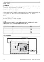
5.5.1.6 Block diagram
Option board
CPU
ϑ
ECU
1
2
3
4
5
6
7
8
9
10
5.5.1.6.1 Input circuit diagram
Digital input, negative switching
A/D converter
or
Comparator
Source configuration
6.9 / 10 / 22 kΩ
Supply voltage Vb2
Digital input
KL30
12/24 V
ECU
Sensor input (negative switching)
GND
5 A slow-blow


