Asentria SiteBoss 571 UserManual
Page 14
Back Panel Ports & Connectors
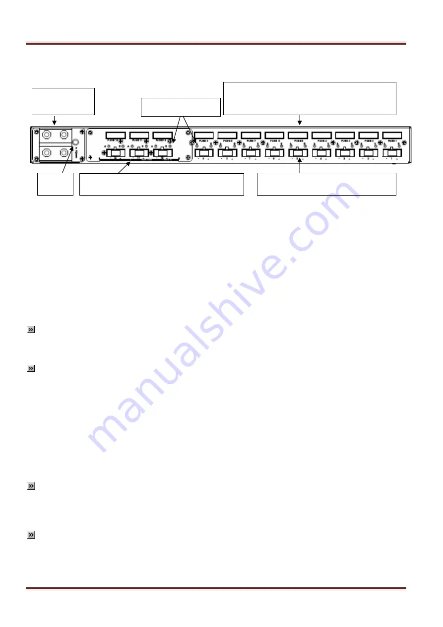
The basic S571 back panel is shown on the next page. Note: the figure below shows the normally empty bay
populated with the 3
– 10-Amp power outputs card.
Fig 8: S571 Back panel ports and connectors
Incoming Power Connection
The Main 48VDC input connector is a dual, two-post, heavy duty terminal block located at rear left side of the
S571. Input voltage range is 40-60VDC, 100Amp maximum. The end user is responsible for providing a protected
DC supply source to the unit input that employs an output circuit breaker or similar current limiting device. The
supply system output circuit breaker/current limiting device should have a rating of 100 Amps maximum. The top
two posts are positive connection, the bottom two posts are negative connection. The user must observe correct
polarity when connecting power to the 48VDC input connector. Reverse polarity protection to connected equipment
is not provided. The internal circuits on the S571 are protected against reverse polarity connection at the back
panel, but other connected equipment may be damaged by such a reverse connection. When input power is
connected correctly, the power LED to right of the 48VDC input connector will light up GREEN. If power is
accidentally connected in reverse polarity, the power LED will light up RED.
Note:
The user must install the power correctly --- reverse polarity protection to equipment connected to
our system is not provided. The Power Controller Board internally protects parts of its circuitry, but other
equipment may be damaged by such a reverse connection.
Remarque: L'utilisateur doit installer le pouvoir correctement --- Protégé contre inversion de polarité de
l'équipement connecté à notre système n'est pas prévu. Le Conseil régulateur de puissance protège
l'intérieur des parties de son circuit, mais d'autres équipements peuvent être endommagés par une telle
connexion inverse.
Power Distribution Output Connectors and Fuses
Nine connectors on the back panel allow devices to be connected to the power distribution outputs. A power
controller board and transistors (MOSFETs) inside the S571 are used to distribute power through each of these
connectors to the powered devices. Each power connector is protected by a GMT fuse
– minimum rating 12A
when runnng loads that approach 10A. Fuses may be provided by Asentria, but normally are provided by the end
user. Asentria recommends using fuses rated at 20% higher current than the expected load.
Note:
The high voltage and current capacity of this unit constitutes an operational hazard. Short-circuits of
connected power circuits may result in fire hazards! DO NOT LEAVE UNINSULATED WIRES EXPOSED! A
qualified technician who can ensure the polarity of connections and that power source is an isolated SELV
(Safety Extra Low Voltage) circuit should perform electrical connections.
Remarque: La haute tension et de la capacité actuelle de cette unité constitue un risque opérationnel. Les
courts-circuits de circuits de puissance connectés peuvent entraîner des risques d'incendie! NE PAS LAISSER
fil non isolés, exposé! Un technicien qualifié qui peut assurer la polarité des connexions et que cette source
d'énergie est un SELV isolé (Safety Extra Low Voltage) circuit doit effectuer les raccordements électriques.
Main 48VDC
input connector
Bay for optional card with one 30-Amp power
output or three 10-Amp power outputs
9
– 10-Amp power distribution output
connectors with LEDs above them
From right to left: #1 thru #9
9
– GMT (minimum rating 12A) fuses for power
distribution outputs
From right to left: #1 thru #9
Power
LED
Power Output LEDs


