3-7
FREQUENCY SYNTHESIS
TESTS
The following tests can be used to verify correct operation of the fre-
quency synthesis circuits. Frequency synthesis testing is divided into
two parts—coarse loop/YIG loop tests and fine loop tests.
Test Setup
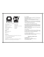
Connect the equipment, shown in Figure 3-2, as fol-
lows:
1. Connect the 690XXB/691XXB rear panel
10 MHz
REF OUT
to the Frequency Counter 10 MHz Ex-
ternal Reference input.
2. Connect the 690XXB/691XXB
RF OUTPUT
to the
Frequency Counter RF Input 1.
Coarse Loop/
YIG Loop Test
Procedure
The following procedure tests both the coarse loop
and YIG loop by stepping the instrument through
its YIG-tuned oscillator’s frequency range in 1 GHz
steps and measuring the RF output at each step.
1. Set up the 690XXB/691XXB as follows:
a. Reset the instrument by pressing
SYSTEM
,
then
Reset
. Upon reset, the CW Menu is dis-
played.
b. Press
Edit F1
to open the current frequency
parameter for editing.
c. Set F1 to the first test frequency indicated on
the Test Record for the model being tested.
3-10
690XXB/691XXB MM
PERFORMANCE
FREQUENCY
VERIFICATION
SYNTHESIS TESTS
6 9 0 X X B / 6 9 1 X X B
F R E Q U E N C Y C O U N T E R
1 0 M H z
E X T I N
1 0 M H z
R E F O U T
R F O U T
I n p u t 1
Figure 3-2.
Equipment Setup for Frequency Synthesis Tests
Summary of Contents for 680 C Series
Page 4: ......
Page 5: ......
Page 13: ...Figure 1 1 Typical Series 690XXB 691XXB Synthesized CW Signal Generator Model 69187B Shown ...
Page 61: ......
Page 97: ......
Page 205: ......
Page 207: ......
Page 221: ......
Page 225: ......
Page 241: ......
Page 259: ......
Page 275: ......
Page 285: ......
Page 289: ......
Page 299: ......
Page 303: ......
Page 315: ......