


3-10
SINGLE SIDEBAND
PHASE NOISE TEST
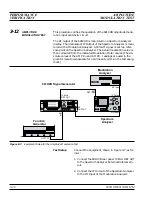
The following test can be used to verify that the 690XXB/691XXB
meets its single sideband phase noise specifications. For this test, a
second 69XXXB is required. This additional instrument acts as a local
oscillator (LO). The CW RF output of the 690XXB/691XXB under test
(DUT) is mixed with the CW RF output from the 69XXXB LO which is
offset by 100 MHz. Single sideband phase noise is measured at offsets
of 10 Hz, 100 Hz, 1 kHz, 10 kHz, 100 kHz, and 1 MHz away from the
resultant 100 MHz IF.
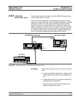
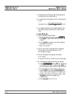
Test Setup
Connect the equipment, shown in Figure 3-5, as fol-
lows:
1. Connect a GPIB interface cable from the PN9000
to the 69XXXB (LO) rear panel
IEEE 488 GPIB
connector.
2. Connect a GPIB interface cable from the PN9000
to the 690XXB/691XXB (DUT) rear panel
IEEE
488 GPIB
connector.
3. Connect the 69XXXB (LO)
RF OUTPUT
to the
LO
INPUT
of the PN9000 Phase Detector module.
4. Connect the 690XXB/691XXB (DUT)
RF OUTPUT
to the
RF INPUT
of the PN9000 Phase Detector
module.
3-20
690XXB/691XXB MM
6 9 X X X B ( L O )
6 9 0 X X B / 6 9 1 X X B ( D U T )
P N 9 0 0 0
P h a s e N o i s e
M e a s u r e m e n t S y s t e m
R E M .
P N 9 0 0 0
P H A S E N O I S E
M E A S U R E M E N T
S Y S T E M
E R R .
M E A S .
B A T T .
S T D B Y
L I N E
O N
S T A T U S
P N 9 0 6 0 - 0 0
D C - 1 0 M H z
N O I S E
O U T P U T
P N 9 4 7 0 - 0 0
N O I S E D E M O D
O U T P U T
L O C K
C O N T R O L
P N 9 4 5 0 - 0 0
T U N E V O L T A G E
O U T P U T
P H A S E
F
+ P / 8
- P / 8
0
+ 1 0 V p 6 0 0
W
-
+ 2 0 V p 6 0 0
W
-
P N 9 3 4 2 - 0 1
5 M H z - 2 6 . 5 G H z
O C X O
C R Y S T A L
O S C I L L A T O R
P H A S E D E T E C T O R
P N 9 5 3 0 - 0 0
F c . T U N E
I N P U T
F c 1 0 0 M H z
O U T P U T
0 / + 1 0 V p + 1 0 H z
-
+ 1 0 d B m 5 0
W
R F I N P U T
E X T E R N A L I N P U T
5 0 0 m V M A X
+ 2 0 d B m M A X
1 0 0
W
- 1 0 / + 1 3 d B m M A X
5 0
W
L O I N P U T
+ 7 d B m M I N
5 0
W
2 n d L O I N P U T
+ 7 d B m M I N
5 0
W
R F S T D
R F H L
m
W A V E
E X T E R N A L
G P I B I n t e r f a c e C a b l e
Figure 3-5.
Equipment Setup for Single Sideband Phase Noise Test
PERFORMANCE
SINGLE SIDEBAND
VERIFICATION
PHASE NOISE TEST
NOTE
The 69XXXB that is used as the lo-
cal oscillator (LO) must have Option
11 (0.1 Hz frequency resolution) in-
stalled.
Summary of Contents for 680 C Series
Page 4: ......
Page 5: ......
Page 13: ...Figure 1 1 Typical Series 690XXB 691XXB Synthesized CW Signal Generator Model 69187B Shown ...
Page 61: ......
Page 97: ......
Page 205: ......
Page 207: ......
Page 221: ......
Page 225: ......
Page 241: ......
Page 259: ......
Page 275: ......
Page 285: ......
Page 289: ......
Page 299: ......
Page 303: ......
Page 315: ......


