


2. Set up the 690XXB/691XXB as follows:
a. Reset the instrument by pressing
SYSTEM
,
then
Reset
. Upon reset the CW Menu is dis-
played.
b. Press
Edit L1
to open the current power level
parameter for editing.
c. Set L1 to the lesser of +10 dBm or the maxi-
mum leveled power level for the instrument
being tested (refer to Table 3-2, page 3-6).
d. Press
Edit F1
to open the current frequency
parameter for editing.
e. Set F1 to 10 MHz.
3. On the Spectrum Analyzer, measure the worst
case harmonic and non-harmonic signals for the
10 MHz carrier. Record their presence by enter-
ing the levels on the Test Record. Refer to Table
3-3 for the specified level limits.
NOTE
Harmonics appear at multiples of the CW
frequency and diminish quickly as the CW
frequency gets greater than 1 GHz.
4. Repeat step 3 with F1 set first to 20 MHz, then
set to 30 MHz. Measure the worst case harmonics
and non-harmonics for each carrier frequency
and record their presence by entering their levels
on the Test Record.
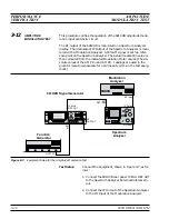
5. Change the Spectrum Analyzer setup as follows:
a. Span: 100 MHz/div
b. CF: 500 MHz
6. Repeat step 3 with F1 set to 40 MHz. Measure
the worst case harmonic and non-harmonic sig-
nals for the 40 MHz carrier and record their pres-
ence by entering their levels on the Test Record.
7. Change the Spectrum Analyzer setup as follows:
a. Span: 200 MHz/div (or maximum span width)
b. CF: 1 GHz (N/A if at maximum span width)
8. Repeat step 3 with F1 set to 350 MHz. Measure
the worst case harmonic and non-harmonic sig-
nals for the 350 MHz carrier and record their
690XXB/691XXB MM
3-13
Harmonic and Harmonic Related:
10 MHz to <100 MHz (Option 21A):
<–40 dBc
³
100 MHz to
£
2.2 GHz (Option 21A): <–50 dBc
10 MHz to
£
50 MHz:
<–30 dBc
>50 MHz to <2 GHz:
<–40 dBc
³
2 GHz (2.2 GHz w/Option 21A)
to
£
20 GHz:
<–60 dBc
>20 GHz to
£
40 GHz:
<–40 dBc
Harmonic and Harmonic Related (Models having a
high-end frequency of >40 GHz and units with Op-
tion 15A at maximum specified leveled output
power):
10 MHz to <100 MHz (Option 21A):
<–40 dBc
³
100 MHz to
£
2.2 GHz (Option 21A): <–50 dBc
10 MHz to
£
50 MHz:
<–30 dBc
>50 Mhz to <2 GHz:
<–40 dBc
³
2 GHz (2.2 GHz w/Option 21A)
to
£
20 GHz:
<–50 dBc
>20 GHz to
£
40 GHz:
<–40 dBc
50 GHz units: >40 GHz to
£
50 GHz:
<–40 dBc
60 GHz units: >40 GHz to
£
60 GHz:
<-30 dBc
65 GHz units: >40 GHz to
£
44 GHz:
<–25 dBc
>44 GHz to
£
65 GHz:
<-30 dBc
Non-Harmonics:
10 MHz to
£
2.2 GHz (Option 21A):
<–60 dBc
10 MHz to <2 GHz:
<–40 dBc
³
2 GHz to
£
65 GHz:
<–60 dBc
Table 3-3.
Spurious Signals Specifications
PERFORMANCE
SPURIOUS SIGNALS TEST: RF OUTPUT SIGNALS
VERIFICATION
£
2 GHz (
£
2.2 GHz UNITS W/OPTION 21A)
Summary of Contents for 680 C Series
Page 4: ......
Page 5: ......
Page 13: ...Figure 1 1 Typical Series 690XXB 691XXB Synthesized CW Signal Generator Model 69187B Shown ...
Page 61: ......
Page 97: ......
Page 205: ......
Page 207: ......
Page 221: ......
Page 225: ......
Page 241: ......
Page 259: ......
Page 275: ......
Page 285: ......
Page 289: ......
Page 299: ......
Page 303: ......
Page 315: ......


