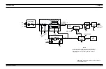


Model 69087B/69187B (SQM P/N 60-141)
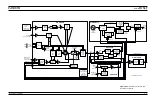
During CW or swept frequency operations in the 40
to 60 GHz frequency range, the 10 to 15 GHz RF
signal input is quadrupled and amplified, then goes
to the modulator. The modulator provides for power
level control and, in the 69187B, amplitude modula-
tion of the RF output signal. From the modulator,
the 40 to 60 GHz RF signals go via a band-pass fil-
ter to the output connector of the SQM.
From the SQM, the 40 to 60 GHz RF output signals
go to the input connector J1 of the forward coupler,
P/N C27184. The other input to the forward coupler
at connector J2 is the 0.01 to 40 GHz RF output sig-
nal from the SDM (0.00001 to 40 GHz RF output
signals from the diplexer for 69087B/69187Bs with
Option 22). From forward coupler output connector
J3, the 0.01 to 60 GHz (0.00001 to 60 GHz for
69087B/69187Bs with Option 22) RF output signals
go to the directional coupler.
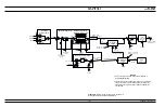
Model 69097B/69197B (SQM P/N 60-142)
During CW or swept frequency operations in the 40
to 65 GHz frequency range, the 10 to 16.25 GHz RF
signal input is qaudrupled and amplified, then goes
to the modulator. The modulator provides for power
level control and, in the 69197B, amplitude modula-
tion of the RF output signals. From the modulator,
the 40 to 65 GHz RF signals go via a band-pass fil-
ter to the output connector of the SQM.
From the SQM, the 40 to 65 GHz RF output signals
go to the input connector J1 of the forward coupler,
P/N C27184. The other input to the forward coupler
at connector J2 is the 0.01 to 40 GHz RFoutput sig-
nals from the SDM (0.00001 to 40 GHz RF output
signals from the diplexer for 69097B/69197Bs with
Option 22). From forward coupler output connector
J3, the 0.01 to 65 GHz (0.00001 to 65 GHz for
69097B/69197Bs with Option 22) RF output signals
go to the directional coupler.
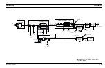
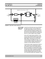
Power Level
Detection/
ALC Loop
The RF output signal from either the switched filter
(
£
20 GHz models), the SDM (
£
40 GHz models), the
diplexer (
£
20 GHz and
£
40 GHz models with Option
22), or the forward coupler (>40 GHz models) goes to
the directional coupler for transfer to the
RF OUT-
PUT
connector. A portion of the RF output signal is
detected and coupled out as feedback to the ALC cir-
cuitry on the A10 ALC PCB. In these circuits, the
signal from the detector is summed with the refer-
2-30
690XXB/691XXB MM
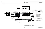
FUNCTIONAL
RF DECK
DESCRIPTION
ASSEMBLIES
Summary of Contents for 680 C Series
Page 4: ......
Page 5: ......
Page 13: ...Figure 1 1 Typical Series 690XXB 691XXB Synthesized CW Signal Generator Model 69187B Shown ...
Page 61: ......
Page 97: ......
Page 205: ......
Page 207: ......
Page 221: ......
Page 225: ......
Page 241: ......
Page 259: ......
Page 275: ......
Page 285: ......
Page 289: ......
Page 299: ......
Page 303: ......
Page 315: ......


