

6-3
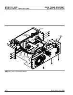
REMOVING AND
REPLACING THE FRONT
PANEL ASSEMBLY
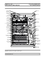
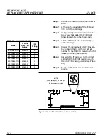
This paragraph provides instructions for removing and replacing the
front panel assembly of the 690XXB/691XXB. The front panel assem-
bly contains the A1 and A2 Front Panel PCBs. Refer to Figure 6-2
during this procedure.
Preliminary
Disconnect the power cord from the unit and remove
the chassis covers as described in paragraph 6-2.
Procedure
Remove and replace the front panel assembly as
follows:
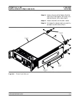
Step 1
Using a Phillips screwdriver, remove the
screws and the front handle assemblies
from the instrument. (For instruments
not having front handles, remove the
screws and the front top and bottom feet
from the instrument.)
Step 2
Remove the rotary knob from the front
panel by pulling straight out on it.
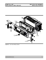
Step 3
Carefully pull the front panel away from
the chassis until the screws attaching the
front panel assembly to the chassis are
accessable.
Step 4
Remove the screws attaching the front
panel assembly to the chassis sides.
Step 5
Disconnect the front panel ribbon cables
from connectors J1 and J22 of the Moth-
erboard.
Step 6
Turn the instrument upside down.
Step 7
Remove the screw attaching the front
panel assembly to the chassis pan.
Step 8
Carefully pull the front panel assembly
forward until it is clear of the
RF OUT-
PUT
connector.
Step 9
If installed, disconnect the coaxial cable
from the front panel assembly connector
A2J13 (FM input) by pulling straight out
on the cable connector.
Step 10
To replace the front panel assembly re-
verse the removal process.
6-6
690XXB/691XXB MM
REMOVAL AND
FRONT PANEL
REPLACEMENT PROCEDURES
ASSEMBLY
NOTE
The screws with green heads have
metric threads. When it becomes
necessary to replace any of these
screws, always use the exact re-
placement green-headed screws
(Anritsu P/N 2000-560) to avoid
damage to the instrument.
Summary of Contents for 680 C Series
Page 4: ......
Page 5: ......
Page 13: ...Figure 1 1 Typical Series 690XXB 691XXB Synthesized CW Signal Generator Model 69187B Shown ...
Page 61: ......
Page 97: ......
Page 205: ......
Page 207: ......
Page 221: ......
Page 225: ......
Page 241: ......
Page 259: ......
Page 275: ......
Page 285: ......
Page 289: ......
Page 299: ......
Page 303: ......
Page 315: ......


