
5-46
690XXB/691XXB MM
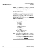
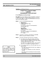
Output Power Level Related Problems
(20 to 40 GHz)
690XXB/691XXB Models with SDM
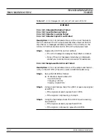
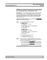
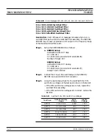
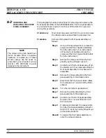
Error 138 SDM Unit or Driver Failed
Description: Error 138 indicates a failure of the SDM ora failure of
the SDM bias regulator or frequency band selection circuitry on the
A14 YIG, SDM, SQM Driver PCB. The 690XXB/691XXB will not pro-
duce an RF output in the 20 to 40 GHz frequency range.
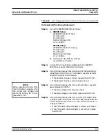
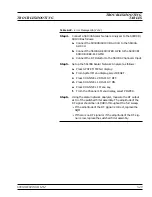
Step 1.
Set up the 690XXB/691XXB as follows:
a. 690XXB Setup:
CW/SWEEP SELECT: Step
F1: 20.000 GHz
F2: 40.000 GHz
Number of Steps: 400
L1: +1.00 dBm
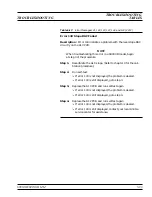
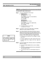
691XXB Setup:
CW/SWEEP SELECT: Analog
F1: 20.000 GHz
F2: 40.000 GHz
Sweep Time: 0.100 Sec
L1: +1.00 dBm
Step 2.
Connect the X input of an oscilloscope to the 690XXB/
691XXB rear panel
HORIZ OUT
connector.
Step 3.
Using the oscilloscope, check for a +8 volts SDM bias voltage
at A14TP7 throughout the full sweep.
q
If the SDM bias voltage is correct, replace the SDM.
q
If the SDM bias voltage is not correct, go to step 4.
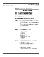
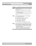
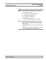
Step 4.
Replace the A14 PCB and run self-test again.
q
If error 138 is not displayed, the problem is cleared.
q
If error 138 is still displayed, contact your local Anritsu
service center for assistance.
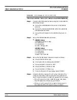
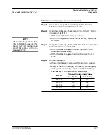
Table 5-22.
Error Messages 138, 139, 140, and 141 (1 of 2)
TROUBLESHOOTING
TROUBLESHOOTING
TABLES
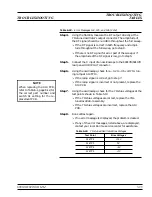
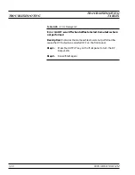
NOTE
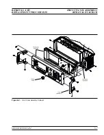
When replacing the A14 PCB,
refer to Table 6-1, page 6-12, for
the correct part number and
switch S1 setting for the re-
placement PCB.
Summary of Contents for 680 C Series
Page 4: ......
Page 5: ......
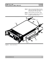
Page 13: ...Figure 1 1 Typical Series 690XXB 691XXB Synthesized CW Signal Generator Model 69187B Shown ...
Page 61: ......
Page 97: ......
Page 205: ......
Page 207: ......
Page 221: ......
Page 225: ......
Page 241: ......
Page 259: ......
Page 275: ......
Page 285: ......
Page 289: ......
Page 299: ......
Page 303: ......
Page 315: ......


