
690XXB/691XXB MM
5-47
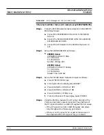
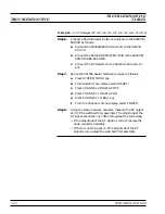
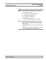
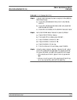
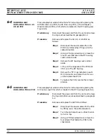
Error 139 32-40 GHz SDM Section Failed
Error 140 25-32 GHz SDM Section Failed
Error 141 20-25 GHz SDM Section Failed
Description: Each of these error messages indicates a failure in a
switched doubler filter path within the SDM. The 690XXB/691XXB
will not produce an RF output in the frequency range of the failed
switched doubler filter path.
Step 1.
Set up the 690XXB/691XXB as follows:
a. 690XXB Setup:
CW/SWEEP SELECT: Step
F1: 2.000 GHz
F2: 40.000 GHz
Number of Steps: 400
L1: +1.00 dBm
691XXB Setup:
CW/SWEEP SELECT: Analog
F1: 2.000 GHz
F2: 40.000 GHz
Sweep Time: 0.100 Sec
L1: +1.00 dBm
Step 2.
Connect the X input of an oscilloscope to the 690XXB/
691XXB rear panel
HORIZ OUT
connector.
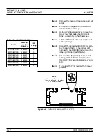
Step 3.
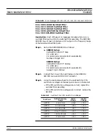
Using the oscilloscope, check the PIN switch drive voltages
at A9TP11, A9TP15, and A9TP24 (shown in Table 5-23).
q
If the PIN switch drive voltages are correct, replace the
SDM.
q
If the PIN switch drive voltages are not correct, replace
the A9 PCB.
Table 5-22.
Error Messages 138, 139, 140, and 141 (2 of 2)
TROUBLESHOOTING
TROUBLESHOOTING
TABLES
Test Point
Active Frequency
Range
Active
Voltage
Inactive
Voltage
A9TP9
0.01 to 20 GHz
+20V
–15V
A9TP11
20 to 25 GHz
+20V
–15V
A9TP15
25 to 32 GHz
+20V
–15V
A9TP24
32 to 40 GHz
+20V
–15V
Table 5-23.
SDM PIN Switch Drive Voltages
Summary of Contents for 680 C Series
Page 4: ......
Page 5: ......
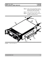
Page 13: ...Figure 1 1 Typical Series 690XXB 691XXB Synthesized CW Signal Generator Model 69187B Shown ...
Page 61: ......
Page 97: ......
Page 205: ......
Page 207: ......
Page 221: ......
Page 225: ......
Page 241: ......
Page 259: ......
Page 275: ......
Page 285: ......
Page 289: ......
Page 299: ......
Page 303: ......
Page 315: ......


