


cies of 2 to 4.4 GHz (refer to Figure 2-8, page 2-27).
This is accomplished by successive binary division of
the 2 to 4.4 GHz RF signal. Phase-lock control of the
2 to 4.4 GHz fundamental frequencies, achieved
prior to down converting, ensures precise control of
the 0.01 to 2.2 GHz frequencies to 1 kHz (0.1 Hz
with Option 11) resolution.
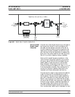
0.01 to 10 MHz (Option 22)
RF output frequencies of 0.01 to 10 MHz are pro-
duced by instruments with Option 22. The 0.01 to
10 MHz signal is generated by the Direct Digital
Synthesizer on the A13 10 MHz DDS PCB, installed
by Option 22. Precise control of the 0.01 to 10 MHz
frequencies to 0.1 Hz resolution is achieved by
phase-lock control of the 26.8435456 MHz signal
from the A5 Fine Loop PCB that is doubled to pro-
duce the clock frequency for the DDS.
Frequency
Modulation
(691XXB only)
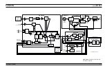
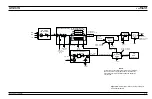
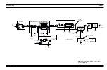
Frequency modulation (FM) of the YIG-tuned oscil-
lator RF output by external signals is performed by
summing the external modulating signal into the
FM control path of the YIG loop. Refer to Figures
2-1 and 2-2. The external modulating signal comes
from the front panel or rear panel
FM IN
input. Cir-
cuits on the A11 FM PCB adjust the modulating sig-
nal for the proper amount of FM for the sensitivity
selected, then sum it into the YIG loop FM control
path. There, it frequency modulates the RF output
signal by controlling the YIG-tuned oscillator's FM
(fine tuning) coil current.
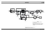
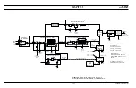
Analog Sweep
Mode
(691XXB only)
Broad-band analog frequency sweeps (>100 MHz
wide) of the YIG-tuned oscillator RF output are ac-
complished by applying appropriate analog sweep
ramp signals, generated by the A12 Analog Instruc-
tion PCB, to the YIG-tuned oscillator's main tuning
coil (via the A14 YIG, SDM, SQM Driver PCB). In
this mode, the start, stop, and bandswitching fre-
quencies are phase-lock-corrected during the sweep.
Narrow-band analog frequency sweeps (
£
100 MHz
wide) of the YIG-tuned oscillator RF output are ac-
complished by summing appropriate analog sweep
ramp signals, generated by the A12 Analog Instruc-
tion PCB, into the YIG-tuned oscillator's FM tuning
coil control path. The YIG-tuned oscillator's RF out-
put is then swept about a center frequency. The cen-
ter frequency is set by applying a tuning signal (also
from the A12 PCB) to the YIG-tuned oscillator's
2-14
690XXB/691XXB MM
FUNCTIONAL
FREQUENCY
DESCRIPTION
SYNTHESIS
NOTE
For 691XXBs with Option 21A at
frequencies of
£
2.2 GHz, broad-band
a n a l o g f r e q u e n c y s w e e p s a r e
>25 MHz wide; narrow-band fre-
quency sweeps are
£
25 MHz
Summary of Contents for 680 C Series
Page 4: ......
Page 5: ......
Page 13: ...Figure 1 1 Typical Series 690XXB 691XXB Synthesized CW Signal Generator Model 69187B Shown ...
Page 61: ......
Page 97: ......
Page 205: ......
Page 207: ......
Page 221: ......
Page 225: ......
Page 241: ......
Page 259: ......
Page 275: ......
Page 285: ......
Page 289: ......
Page 299: ......
Page 303: ......
Page 315: ......


