5-40
690XXB/691XXB MM
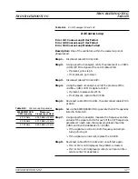
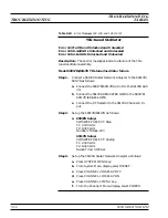
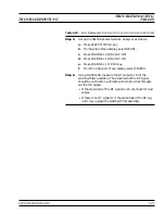
Step 6.
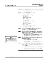
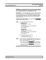
Connect a 56100A Scalar Network Analyzer to the 690XXB/
691XXB as follows:
a. Connect the 690XXB/691XXB
AUX I/O
to the 56100A
AUX I/O
.
b. Connect the 56100A
DEDICATED GPIB
to the 690XXB/
691XXB
IEEE-488 GPIB
.
c.
Connect the RF Detector to the 56100A Channel A In-
put.
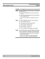
Step 7.
Set up the 56100A Scalar Network Analyzer as follows:
a. Press SYSTEM MENU key.
b. From System Menu display, select RESET.
c.
Press CHANNEL 2 DISPLAY: OFF
d. Press CHANNEL 1 DISPLAY: ON
e.
Press CHANNEL 1 MENU key.
f.
From the Channel 1 Menu display, select POWER.
Step 8.
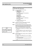
Using the scalar network analyzer, measure the RF output
at J3 of the switched filter assembly. The amplitude of the
RF signal should be >+17 dBm throughout the full sweep.
q
If the amplitude of the RF signal is correct, replace the
down converter assembly.
q
If there is no RF signal or if the amplitude of the RF
signal is low, replace the switched filter assembly.
Table 5-20.
Error Messages 128, 129, 130, 131, 132, 133, 134, and 135 (3 of 8)
TROUBLESHOOTING
TROUBLESHOOTING
TABLES
Summary of Contents for 680 C Series
Page 4: ......
Page 5: ......
Page 13: ...Figure 1 1 Typical Series 690XXB 691XXB Synthesized CW Signal Generator Model 69187B Shown ...
Page 61: ......
Page 97: ......
Page 205: ......
Page 207: ......
Page 221: ......
Page 225: ......
Page 241: ......
Page 259: ......
Page 275: ......
Page 285: ......
Page 289: ......
Page 299: ......
Page 303: ......
Page 315: ......


