


4-6
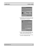
INITIAL SETUP
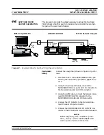
The 690XXB/691XXB is calibrated using an IBM compatible PC and
external test equipment. The PC must have the Windows 3.1, Win-
dows 95, or Windows 98 operating system installed and be equipped
with a mouse. Initial setup consists of interfacing the PC to the
690XXB/ 691XXB.
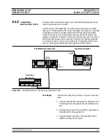
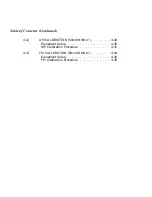
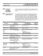
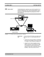
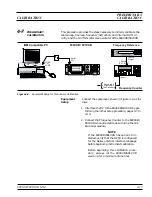
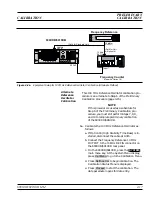
Interconnec-
tion
Using the Anritsu P/N T1678 serial interface assem-
bly, connect the PC to the 690XXB/691XXB as fol-
lows:
1. Connect the wide flat cable between the 690XXB/
691XXB rear panel
SERIAL I/O
connector and the
P1 connector on the T1678 serial interface PCB.
2. Connect the narrow flat cable between the P2
(TERM) connector on the T1678 serial interface
PCB and the COM1 or COM2 connector on the
PC. Use the RJ11-to-DB-9 or RJ11-to-DB-25
adapter, provided with the T1678 serial interface
assembly, to make the connection at the PC.
690XXB/691XXB MM
4-7
CALIBRATION
INITIAL SETUP
I B M - C o m p a t i b l e P C
T o
6 9 0 X X B / 6 9 1 X X B
T o
P C
P 1
P 2
P 3
T e r m
T 1 6 7 8 S e r i a l I n t e r f a c e
6 9 0 X X B / 6 9 1 X X B
C O M 1
o r
C O M 2
S e r i a l
I / O
Figure 4-1.
PC to 690XXB/691XXB Interconnection for Calibration
Summary of Contents for 680 C Series
Page 4: ......
Page 5: ......
Page 13: ...Figure 1 1 Typical Series 690XXB 691XXB Synthesized CW Signal Generator Model 69187B Shown ...
Page 61: ......
Page 97: ......
Page 205: ......
Page 207: ......
Page 221: ......
Page 225: ......
Page 241: ......
Page 259: ......
Page 275: ......
Page 285: ......
Page 289: ......
Page 299: ......
Page 303: ......
Page 315: ......


