


0.01 to 2.2 GHz
Digital Down
Converter
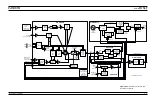
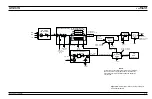
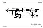
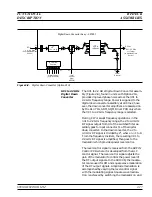
The 0.01 to 2.2 GHz Digital Down Converter assem-
bly (Figure 2-8), found in units with Option 21A,
provides improved phase noise across the 0.01 to
2.2 GHz frequency range. Power is supplied to the
digital down converter assembly at all times; how-
ever, the down converter amplifiers are powered on
by the A14 YIG, SDM, SQM Driver PCB only when
the 0.01 to 2.2 GHz frequency range is selected.
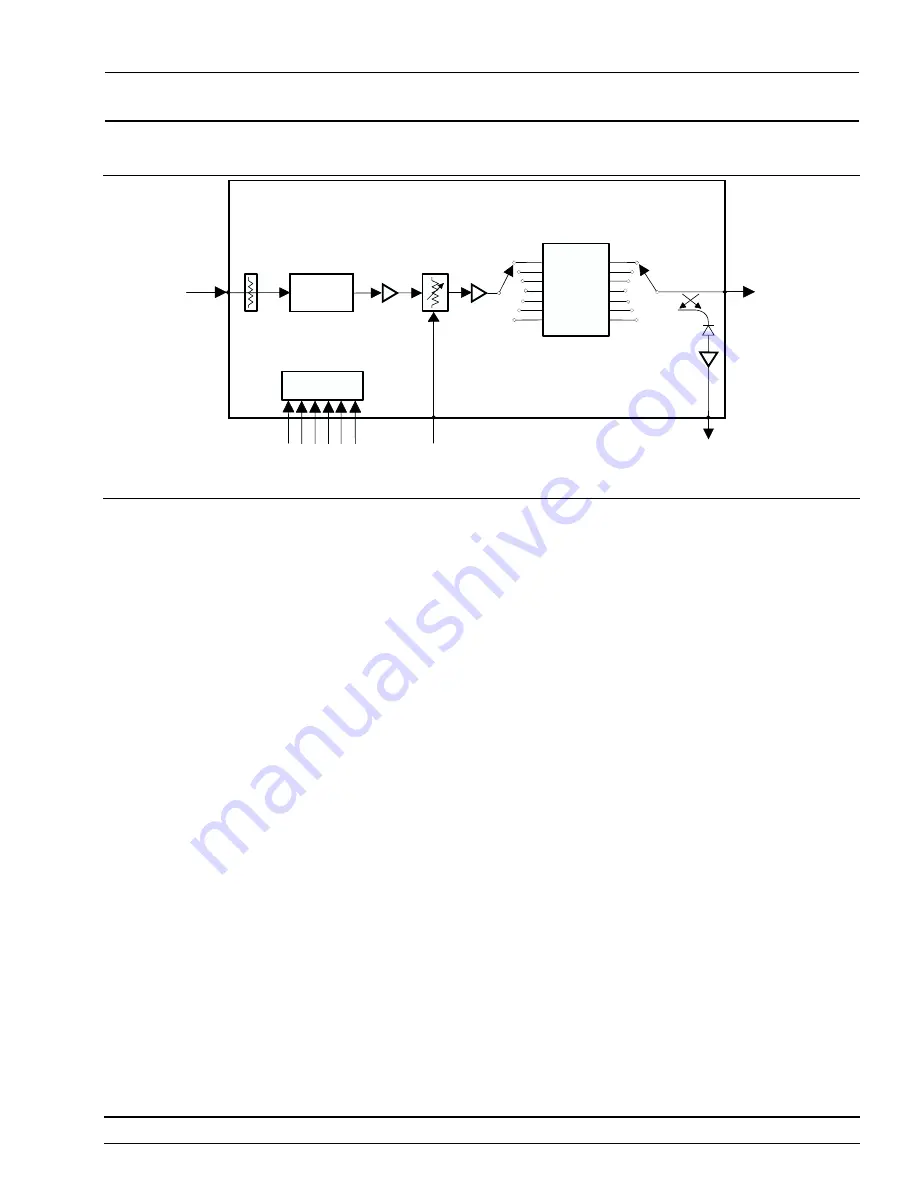
During CW or swept frequency operations in the
0.01 to 2.2 GHz frequency range, the 2 to 4.4 GHz
RF signal output from J3 of the switched filter as-
sembly goes to input connector J1 of the digital
down converter. In the down converter, the 2 to
4.4 GHz RF signal is divided by 2
n
, where n = 1 to 8.
From the frequency dividers, the resulting 0.01 to
2.2 GHz RF signal is amplified, then goes to the
modulator which provides power level control.
The level control signal is received from the A9 PIN
Control PCB where it is developed from the ALC
control signal. The level control signal adjusts the
gain of the modulator to control the power level of
the RF output signals. In the 691XXB, the modula-
tor is also used for AM and square wave modulation
of the RF output signals. Amplitude modulation is
accomplished by varying the level control signal
with the modulating signal. Square wave modula-
tion is achieved by switching the modulator on and
690XXB/691XXB MM
2-27
FUNCTIONAL
RF DECK
DESCRIPTION
ASSEMBLIES
L e v e l
D e t e c t o r
2 . 0 - 4 . 4 G H z
J 3
D i g i t a l D o w n C o n v e r t e r A s s y . - 5 0 7 2 2 - 1
J 1
L e v e l
C o n t r o l
( f r o m
A 9 P C B )
R F I n
( f r o m S w i t c h e d F i l t e r
P o r t J 3 )
R F O u t
D i g i t a l C o n t r o l
( f r o m A 1 4 P C B )
P 1
P 1
J 6
¸
2
n
( n = 1 t o 8 )
R F S w i t c h
C o n t r o l s
L P F s
1 6 B a n d s
0 . 0 1 - 2 . 2 G H z
> + 1 7 d B m
( t o S w i t c h e d F i l t e r
P o r t J 1 )
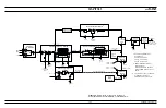
Figure 2-8.
Digital Down Converter (Option 21A)
Summary of Contents for 680 C Series
Page 4: ......
Page 5: ......
Page 13: ...Figure 1 1 Typical Series 690XXB 691XXB Synthesized CW Signal Generator Model 69187B Shown ...
Page 61: ......
Page 97: ......
Page 205: ......
Page 207: ......
Page 221: ......
Page 225: ......
Page 241: ......
Page 259: ......
Page 275: ......
Page 285: ......
Page 289: ......
Page 299: ......
Page 303: ......
Page 315: ......


