5-4
MALFUNCTIONS NOT
DISPLAYING AN ERROR
MESSAGE
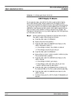
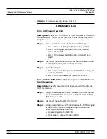
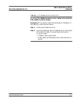
The 690XXB/691XXB must be operating to run self-test. Therefore,
malfunctions that cause the instrument to be non-operational do not
produce error messages. These problems generally are a failure of the
690XXB/691XXB to power up properly. Table 5-4, beginning on page
5-12, provides troubleshooting procedures for these malfunctions.
5-5
TROUBLESHOOTING
TABLES
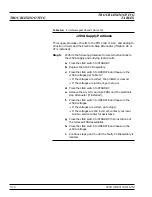
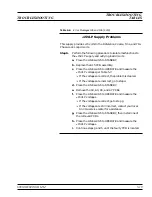
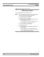
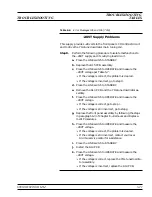
Tables 5-4 through 5-24, beginning on page 5-12, provide procedures
for isolating malfunctions to a replaceable subassembly or RF compo-
nent. In those cases where any of several subassemblies or RF compo-
nents could have caused the problem, subassembly/RF component re-
placement is indicated. The recommended replacement order is to
replace first the subassemblies/RF components that are most likely to
have failed.
Figure 5-1, on the following page, shows the location of the 690XXB/
691XXB connectors and test points that are called out in the trouble-
shooting procedures of Tables 5-4 through 5-24.
CAUTION
Never remove or replace a subassembly or RF component
with power applied. Serious damage to the instrument may
occur.
5-10
690XXB/691XXB MM
MALFUNCTIONS NOT DISPLAYING
TROUBLESHOOTING
AN ERROR MESSAGE
Summary of Contents for 680 C Series
Page 4: ......
Page 5: ......
Page 13: ...Figure 1 1 Typical Series 690XXB 691XXB Synthesized CW Signal Generator Model 69187B Shown ...
Page 61: ......
Page 97: ......
Page 205: ......
Page 207: ......
Page 221: ......
Page 225: ......
Page 241: ......
Page 259: ......
Page 275: ......
Page 285: ......
Page 289: ......
Page 299: ......
Page 303: ......
Page 315: ......


