


Power Sweep
In this mode, the CPU has the ALC step the RF out-
put through a range of levels specified by the user.
This feature can be used in conjunction with the
sweep mode to produce a set of identical frequency
sweeps, each with a different RF power output level.
Amplitude
Modulation
(691XXB only)
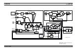
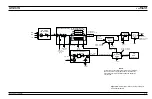
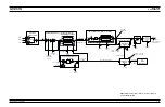
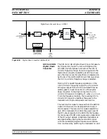
Amplitude modulation (AM) of the RF output signal
by an external signal is accomplished by summing
the external modulating signal into the ALC loop.
External modulating signals come from the front
panel or rear panel
AM IN
inputs. On the A10 PCB,
the AM Input Sensitivity DAC and the AM Calibra-
tion DAC, under the control of the CPU, adjust the
modulating signal for the proper amount of AM in
both the linear (log amp in) and the log (log amp
out) modes of operation. The adjusted modulating
signal is summed with the level reference, slope,
and detector inputs into the ALC loop. This pro-
duces an ALC control signal that varies with the
modulating signal. The action of the ALC loop then
causes the envelope of the RF output signal to track
the external modulation signal.
Square Wave
Modulation
(691XXB only)
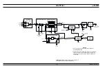
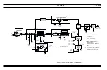
Square wave modulation is accomplished by turning
the RF output signal on and off using internally
generated square wave or external square wave in-
puts.
The A6 Square Wave Generator PCB, under control
of the CPU, divides the 10 MHz reference signal
received from the A5 Fine Loop PCB to produce
square waves. These internal square wave signals
are fed to the A9 PIN Control PCB. There they are
multiplexed with the external square wave signals
received from the front or rear panel. The output of
the multiplexer is two sample/hold signals. One goes
via a pulse level shift circuit to the ALC modulator
driver to modulate the RF output signal; the other
goes to the A10 ALC PCB to cause the level ampli-
fier to operate as a sample/hold amplifier. The am-
plifier is synchronized with the modulating signal so
that the ALC loop effectively operates only during
the ON portion of the modulated RF output signal.
2-18
690XXB/691XXB MM
FUNCTIONAL
ALC AND
DESCRIPTION
MODULATION
Summary of Contents for 680 C Series
Page 4: ......
Page 5: ......
Page 13: ...Figure 1 1 Typical Series 690XXB 691XXB Synthesized CW Signal Generator Model 69187B Shown ...
Page 61: ......
Page 97: ......
Page 205: ......
Page 207: ......
Page 221: ......
Page 225: ......
Page 241: ......
Page 259: ......
Page 275: ......
Page 285: ......
Page 289: ......
Page 299: ......
Page 303: ......
Page 315: ......


