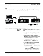
6. Calibrate the 100 MHz Reference Oscillator as
follows:
a. If Option 16 (High Stability Time Base) is in-
stalled, disconnect the cable at A3J6.
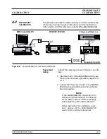
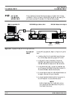
b. Connect the Frequency Counter to the
690XXB/691XXB RF output connector .
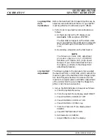
c. At the
$
prompt, type:
calterm 130
and
press <ENTER>.
d. Follow the instructions on the screen.
e. Reconnect the cable to A3J6, if removed.
f. If Option 16 is installed, use a Phillips screw-
driver and remove the screw on top of the
10 MHz High Stability Crystal Oscillator as-
sembly to gain access the timebase adjustment
screw.
g. On the 690XXB/691XXB, press
SYSTEM
,
then
Reset
. Upon reset the CW Menu is dis-
played.
h. Press
Edit F1
to open the current frequency
parameter for editing.
i. Set F1 to 10 GHz (5 GHz for model 69017B/
69117B).
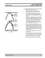
j. Using a Phillips screwdriver, adjust the time-
base to obtain a frequency counter reading of
exactly 10 GHz (5 GHz for model 69017B/
69117B).
k. Record step completion on the Test Record.
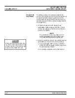
7. Calibrate the Ramp Center DAC as follows:
a. At the
$
prompt, type:
calterm 129
and
press <ENTER>. (The
$
prompt will appear on
the screen when the calibraton is complete.)
b. Record step completion on the Test Record.
8. Calibrate the Sweep Width DAC as follows:
a. At the
$
prompt, type:
calterm 133
and
press <ENTER>. (The
$
prompt will appear on
the screen when the calibration is complete.)
b. Record step completion on the Test Record.
690XXB/691XXB MM
4-15
PRELIMINARY
CALIBRATION
CALIBRATION
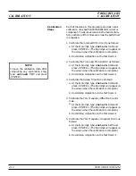
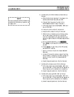
NOTE
For an alternate 100 MHz Reference
Oscillator Calibration procedure, go
to page 4-17.
Summary of Contents for 680 C Series
Page 4: ......
Page 5: ......
Page 13: ...Figure 1 1 Typical Series 690XXB 691XXB Synthesized CW Signal Generator Model 69187B Shown ...
Page 61: ......
Page 97: ......
Page 205: ......
Page 207: ......
Page 221: ......
Page 225: ......
Page 241: ......
Page 259: ......
Page 275: ......
Page 285: ......
Page 289: ......
Page 299: ......
Page 303: ......
Page 315: ......


