


(2) Press
CTRL + F
to transfer this value
automatically to the 69XXXB (LO). A very
low frequency beat (<10 Hz) should be ob-
tained, indicating that the correct carrier
frequency (on the 690XXB/ 691XXB DUT)
is programmed.
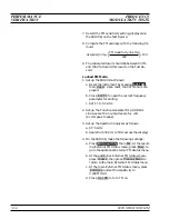
4. Calibrate and lock the PN9000 as follows:
a. Offset the frequency of either the 69XXXB
(LO) or 690XXB/691XXB (DUT) as follows:
(1) Press
Local
to return the 690XXB/
691XXB to local control.
(2) Offset the frequency by 1 kHz.
b. On the PN9000, select the Calib./Exec Cal
menu, then select OK.
c. After calibration, repeat step a to remove the
1 kHz offset.
d. On the PN9000, select the Lock/Def. Loop
menu:
(1) Set Loop BW = 100 Hz.
e. Select the Lock/AutoLock menu:
(1) Set Vmin = 0V
(2) Set Vmax = 10V
(3) Select OK to perform the automatic lock-
ing process.
The system will check that conditions for lock-
ing are OK, measure the tune slope of the ref-
erence source,and look for the locking voltage.
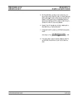
5. On the PN9000, perform the single sideband
phase noise measurement as follows:
a. Select the Measure menu, then select OK to
perform the measurement.
6. Record the displayed phase noise levels at 10 Hz,
100 Hz, 1 kHz, 10 kHz, 100 kHz, and 1 MHz off-
set from the carrier frequency on the Test Record.
7. Repeat steps 3 through 6 for all frequencies listed
on the Test Record.
690XXB/691XXB MM
3-23
PERFORMANCE
SINGLE SIDEBAND
VERIFICATION
PHASE NOISE TEST
CW Carrier
Frequency
Offset From
Carrier
Test
Specification
>2.21 GHz to
£
6.0 GHz
10 Hz
100 Hz
1 kHz
10 kHz
100 kHz
1 MHz
<–50 dBc*
<–80 dBc
<–107 dBc
<–110 dBc
<–107 dBc
<–130 dBc
>6.0 GHz to
£
10.0 GHz
10 Hz
100 Hz
1 kHz
10 kHz
100 kHz
1 MHz
<–45 dBc*
<–75 dBc
<–104 dBc
<–107 dBc
<–107 dBc
<–128 dBc
>10.0 Ghz to
£
20.0 GHz
10 Hz
100 Hz
1 kHz
10 kHz
100 kHz
1 MHz
<–39 dBc*
<–69 dBc
<–98 dBc
<–104 dBc
<–102 dBc
<–125 dBc
>20 GHz to
£
40.0 GHz
10 Hz
100 Hz
1 kHz
10 kHz
100 kHz
1 MHz
<–33 dBc*
<–63 dBc
<–92 dBc
<–98 dBc
<–96 dBc
<–119 dBc
* Add 8 dB to the 10 Hz offset specificaton if
Option 16 (High-Stability Time Base) is installed.
Table 3-5.
Single Sideband Phase Noise
Test Specification
Summary of Contents for 680 C Series
Page 4: ......
Page 5: ......
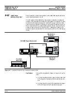
Page 13: ...Figure 1 1 Typical Series 690XXB 691XXB Synthesized CW Signal Generator Model 69187B Shown ...
Page 61: ......
Page 97: ......
Page 205: ......
Page 207: ......
Page 221: ......
Page 225: ......
Page 241: ......
Page 259: ......
Page 275: ......
Page 285: ......
Page 289: ......
Page 299: ......
Page 303: ......
Page 315: ......


