


4-4
CALIBRATION
FOLLOWING
SUBASSEMBLY
REPLACEMENT
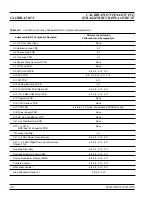
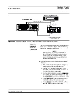
Table 4-2 (page 4-6) lists the calibration that should be performed fol-
lowing the replacement of 690XXB/691XXB subassemblies or RF com-
ponents.
4-5
CONNECTOR AND KEY
LABEL NOTATION
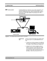
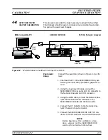
The calibration procedures include many references to equipment in-
terconnections and control settings. For all 690XXB/691XXB refer-
ences, specific labels are used to denote the appropriate menu key,
data entry key, data entry control, or connector (such as
CW/SWEEP
SELECT
or
RF OUTPUT
). Most references to supporting test equip-
ment use general labels for commonly used controls and connections
(such as Span or RF Input). In some cases, a specific label is used that
is a particular feature of the test equipment listed in Table 4-1.
4-4
690XXB/691XXB MM
CALIBRATION FOLLOWING
CALIBRATION
SUBASSEMBLY REPLACEMENT
INSTRUMENT
CRITICAL
SPECIFICATION
RECOMMENDED
MANUFACTURER/MODEL
PROCEDURE
NUMBER
Frequency Counter
Frequency Range: 1 to 40 GHz
Input Impedance: 50
W
Resolution: 1 Hz
Anritsu Model MF2414A
4-7
Spectrum Analyzer
Frequency Range: 1 to 5 GHz
Resolution Bandwidth: 10 Hz
Tektronix, Model 2794
4-13
Power Meter
with
Power
Sensors
Power Range: –30 to +20 dBm
(1
m
W to 100 mW)
Anritsu Model ML2437A or ML2438A,
with
Power Sensors:
MA2474A (0.01 to 40 GHz)
MA2475A (0.01 to 50 GHz)
4-12
Frequency Reference
Frequency: 10 MHz
Accuracy: 5
´
10
–12
parts/day
Absolute Time Corp., Model 300
4-7
Function Generator
Output Voltage: 2 volts peak-to-peak
Functions: 0.4 Hz to 100 kHz sine and
square waveforms
Hewlett-Packard, Model 33120A
4-12. 4-13
Digital Multimeter
Resolution: 4-1/2 digits (to 20V)
DC Accuracy: 0.002% +2 counts
DC Input Impedance: 10 M
W
AC Accuracy: 0.07% +100 counts
(to 20 kHz)
AC Input Impedance: 1 M
W
John Fluke, INC., Model 8840A, with
Option 8840A-09K (True RMS AC)
4-12, 4-13
Scalar Network
Analyzer, with
RF Detector
Frequency Range: 0.01 to 60 GHz
Anritsu Model 56100A, with
RF Detector:
560-7K50 (0.01 to 40 GHz)
560-7VA50 (0.01 to 50 GHz)
SC5198 (40 to 60 GHz)
4-8, 4-10
Attenuator
Frequency Range: DC to 40 GHz
Max Input Power: >+17 dBm
Attenuation: 10 dB
Anritsu, Model 41KC-10
4-8, 4-10
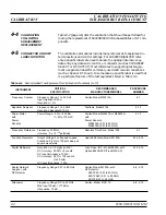
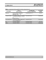
Table 4-1.
Recommended Test Equipment for Calibration Procedures (1 of 2)
Summary of Contents for 680 C Series
Page 4: ......
Page 5: ......
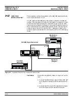
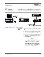
Page 13: ...Figure 1 1 Typical Series 690XXB 691XXB Synthesized CW Signal Generator Model 69187B Shown ...
Page 61: ......
Page 97: ......
Page 205: ......
Page 207: ......
Page 221: ......
Page 225: ......
Page 241: ......
Page 259: ......
Page 275: ......
Page 285: ......
Page 289: ......
Page 299: ......
Page 303: ......
Page 315: ......


