


Chapter 3
Geometries with no orientation support
98
Rockwell Automation Publication MOTION-UM002F-EN-P - February 2018
See also
Calibrate a Delta Two-dimensional robot
Calibrate a Delta two-dimensional robot using the same method for calibrating a
Delta three-dimensional robot. Obtain the angle values from the robot
manufacturer for J1 and J2 at the calibration position. Use these values to
establish the reference position.
See also
Calibrate a Delta Three-dimensional robot
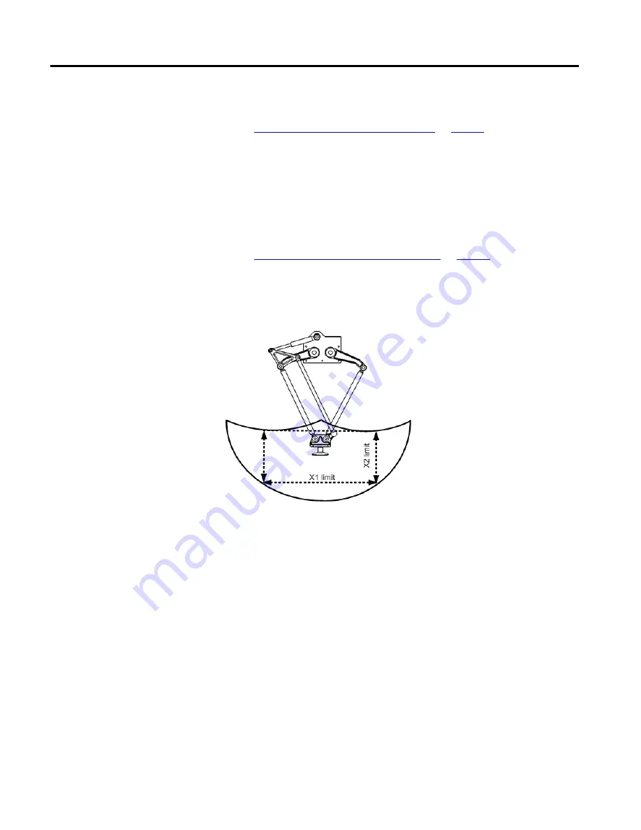
The work envelope is the two-dimensional region of space that defines the
reaching boundaries for the robot arm. The typical working envelope for a
two-dimensional Delta robot is a boundary composed of circular arcs.
Program the parameters for the two-dimensional Delta robot within a rectangle,
dotted lines in the illustration, inside the robots work zone. Define the rectangle
by the positive and negative dimensions of the X1, X2 virtual source axes. Be sure
that the robot position does not go outside the rectangle. Check the position in
the event task.
To avoid problems with singularity positions, the Logix Designer application
internally calculates the joint limits for the Delta robot geometries. When an
MCT instruction is invoked for the first time, the maximum positive and
maximum negative joint limits are internally calculated based upon the link
lengths and offset values entered on the
Geometry
and
Offsets
tabs of the
Coordinate System Properties
dialog box.
For more information about maximum positive and negative joint limits, see
Maximum positive joint limit condition and Maximum negative joint limit
condition.
Calibrate a Delta
Two-dimensional robot
Identify the work envelope for
a Delta Two-Dimensional robot